Drawing Layer Properties Advanced Tab
In the drawing layer's Layer Properties dialog box, you will find an Advanced tab containing some very useful options:
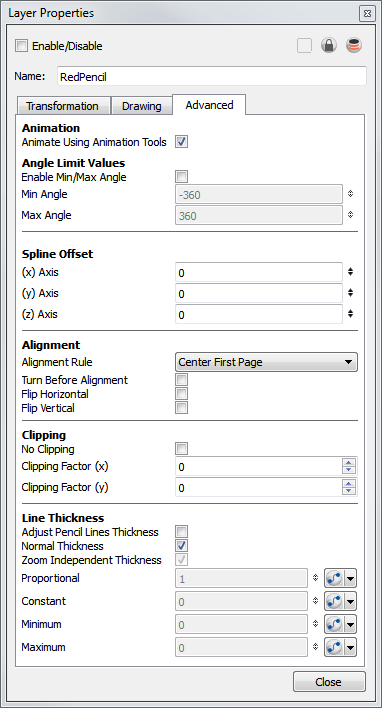
Animation
|
•
|
Animate Using Animation Tools: By default, a drawing layer can be animated, but Toon Boom Animate Pro gives you the ability to disable this feature. Being able to switch your drawings so they can no longer be animated without a peg has certain advantages. It means that you can have access to the drawing substitution feature for this drawing layer, while being able to create keyframes on its parent peg. This feature is also available for backward compatibility when bringing in templates created in older versions of the software, so as not to lose their offset keyframes or drawing substitution keyframes. |
Refer to the
Cut-out Animation chapter to learn more about the Animate Using Animation Tools option.
Angle Limit Value
Use this section to set a maximum and minimum rotation angle for your drawing. You will mainly use the option for a cut-out character when you do not want an elbow to bend too far in or too far out.
|
•
|
Enable Min/Max Angle: Enable this option if you want to activate the minimum and maximum angle constraints. |
|
•
|
Min Angle: Type the minimum angle you want the drawing to rotate too. |
|
•
|
Max Angle: Type the maximum angle you want the drawing to rotate too. |
Spline Offset
In the X, Y and Z axis fields, type the coordinates of where you want to offset the visual trajectory. By default, the trajectory is displayed at the centre of the Camera view. If you want to move it so it corresponds better with your drawing, either type new coordinates or use the Spline Offset  tool available in the Advanced Animation toolbar.
To display the trajectory in the Camera view, select your drawing and select View > Show > Control.
Alignment
|
•
|
Alignment Rule: The alignment rule selections are intended to deal with drawings that were created on paper of a different size or orientation from the default alignment rule (set up in the Scene Setting dialog box). If you select Turn Before Alignment, the drawings are rotated and then scaled, based on the option selected from the drop-down list. The drawings are then scaled to match Toon Boom Animate Pro alignment rectangle. |
|
•
|
Left: The default alignment for drawings; aligns the drawings on the left side of the scene’s alignment rectangle. Toon Boom Animate Pro scales the drawings to match their height to the alignment rectangle of the scene. |
|
•
|
Right: Aligns the drawings on the right side of the alignment rectangle. Toon Boom Animate Pro scales the drawings to match their height to the height of the alignment rectangle of the scene. |
|
•
|
Top: Aligns the drawings on the top of the alignment rectangle. Toon Boom Animate Pro scales the drawings to match their widths to the width of the alignment rectangle of the scene. |
|
•
|
Bottom: Aligns the drawings on the bottom of the alignment rectangle. Toon Boom Animate Pro scales the drawings to match their widths to the width of the alignment rectangle of the scene. |
|
•
|
Centre Fit: Centres the drawings. |
|
•
|
Centre Fill: Centres the drawings and then scales them so that the width or height fills the available space. |
|
•
|
Centre LR: Aligns the drawings in the left-right centre of the alignment rectangle. Toon Boom Animate Pro scales the drawings to match their height to the height of the alignment rectangle of the scene. |
|
•
|
Centre TB: Aligns the drawings in the top-bottom centre of the alignment rectangle. Toon Boom Animate Pro scales the drawings to match their widths to the width of the alignment rectangle of the scene. |
|
•
|
Stretch: Scales the drawings so that they fit within the alignment rectangle of the scene. This is particularly useful for images that you will manipulate with a Quadmap module. If the drawings in the Quadmap module do not have the same aspect ratio as the alignment rectangle of the scene (from the Scene Settings dialog box), the handles on the quadmap will not appear on the corners of the image, making it difficult to manipulate the quadmap. In this case, you would set the drawing layer of the quadmap images to Stretch so that the handles appear on the corner of the image. This can have the effect of distorting the images, but this is not an issue with images that will be distorted through the Quadmap module anyway. |
|
•
|
As Is: Leaves the drawings aligned as they are. |
|
•
|
Centre First Page: Aligns the centre of the first part of a standard pan cel with the centre of the field chart. |
|
•
|
Turn Before Alignment: This option rotates the drawings in the selected element 90 degrees to the left before scaling and aligning them according to the alignment rule, and before performing any offset, rotation or scaling for the element or the peg. This and the Alignment Rule are intended for drawings that were created on paper of a different size or orientation than the other paper in the scene, and requires alignment so as to be able to accurately treat them. |
|
•
|
Flip Horizontal: Flips the drawing on the X-axis. |
|
•
|
Flip Vertical: Flips the drawing on the Y-axis. |
Clipping
|
•
|
No Clipping: Select this option if you do not want to clip the images in this module before an effect is applied to it. |
|
•
|
Clipping Factor (X)/(Y): This is an option for rendering images that are larger than the final frame. With this option enabled, images can be moved by an Apply Peg Transformation module without black entering into the composite as a result of early clipping. In addition, this option is useful for images that have a blur that should appear in the frame even though the image itself is not in frame. |
Line Thickness
|
•
|
Adjust Pencil Lines Thickness: Enable this option if you are working with pencil lines. If you do not check this option and are working with pencil lines, you will not see any changes to your lines in the Camera view, in the Render mode after making adjustments in the Layer Properties panel. |
|
•
|
Normal Thickness: Disables all overrides on the Line Thickness.
|
|
•
|
Zoom Independent Thickness: Select this if you do not want to display line thickness in proportion the amount of zoom in the view window. Everything else will increase in size, but the line thickness will stay the same. |
|
•
|
Proportional: Enter a multiple by which you want to increase the line thickness. Entering 1 will result in no change; entering 0 (zero) will hide the lines. |
|
•
|
Constant: Enter a value in pixels (based on a 740x540 screen resolution) at which to maintain the line thickness. |
|
•
|
Minimum: Enter a value in pixels (based on a 74 x540 screen resolution) for the minimum line thickness allowed. |
|
•
|
Maximum: Enter a value in pixels (based on a 740x540 screen resolution) for the maximum line thickness allowed. |
To modify the line thickness:
|
•
|
The lines must be converted to Colour Art (select Drawing > Create Colour Art from Line Art). |
|
•
|
To view this feature in the Camera view, you must first activate the Enable Variable Line Thickness option, found in the OpenGL tab in the Preferences panel. |
Related Topics