


Deformer Effects
There are
To understand the various parameters better, you should know the following terms:
| • | Radius: The radius determines the size of a zone. The radius value is the length from the central point of the zone to its edge. By increasing the radius value, you increase the size of the area. |

| • | Transversal: The transversal parameter is related to the width of the zone in relation to the bone. The transversal value cuts across the bone. |
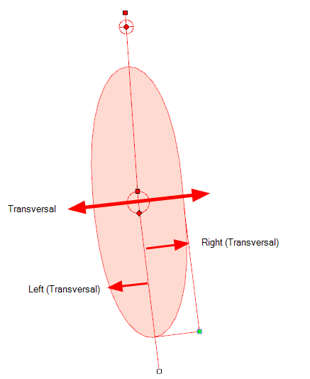
| • | Longitudinal: The longitudinal parameter is related to the length of the zone in relation to the bone. The longitudinal value is parallel to the bone's length. |

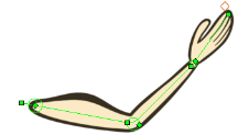
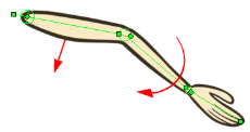
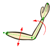
The Articulation module is used between two bones to create a joint where the limb or element will rotate.
When you create a bone structure using the Rigging ![]() tool, an Articulation module is automatically added between every two bones you create. You can also add an Articulation module to your Bone deformation effect in the network to add a supplementary articulation to any existing limb previously built. This module can also be used to manually build a bone structure. The Articulation module works best when inserted between two Bone modules—see Bone Deformer.
tool, an Articulation module is automatically added between every two bones you create. You can also add an Articulation module to your Bone deformation effect in the network to add a supplementary articulation to any existing limb previously built. This module can also be used to manually build a bone structure. The Articulation module works best when inserted between two Bone modules—see Bone Deformer.
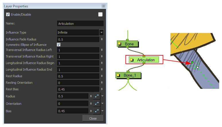
If you adjust your rig in Setup mode with the Transform tool, it will adjust these parameters for you—see Setting Up the Resting Position. However, you can manually set the Articulation effect module parameters in the Layer Properties dialog:
| Parameter | Description | ||||||
| Name | Use this field to rename the module. | ||||||
| Influence Type | Lets you choose a zone of influence type. This is the area of the drawing surrounding the deformer which will be influenced (deformed) by the deformation. | ||||||
| Influence Fade Radius | Enter the your Fade Radius value for the Zone of Influence. You can also use the up and down arrow buttons to select a value. | ||||||
| Symmetric Ellipse of Influence |
This option is enabled by default. The shape of the ellipse will be symmetrical on both transversal and longitudinal radius. The following will happen:
Note: If you want to define individual values for these, then deselect the Symmetric Ellipse of Influence option and enter the values required for each. |
||||||
| Transversal Influence Radius Left | When the Symmetric Ellipse of Influence option is enabled, this field controls both the Left and Right Transversal Radius values. When the option is disabled, enter the value in this field to control the size of the Left Transversal Radius. | ||||||
| Transversal Influence Radius Right | When the Symmetric Ellipse of Influence option is enabled, the value in this field will be unused. When the option is disabled, enter the value in this field to control the size of the Right Transversal Radius. | ||||||
| Longitudinal Influence Radius Begin | When the Symmetric Ellipse of Influence option is enabled, the value in this field will be unused.When the option is disabled, enter the value in this field to control the size of the radius at the beginning of the deformer. | ||||||
| Longitudinal Influence Radius End | When the Symmetric Ellipse of Influence option is enabled, this field controls both the End and Begin longitudinal radius values. When the option is disabled, enter the value in this field to control the size of the radius at the end of the deformer. | ||||||
| Rest Radius | Lets you set the resting radius of the articulation (size of the circle). | ||||||
| Resting Orientation | Lets you set the resting rotation angle value of the articulation. | ||||||
| Rest Bias | Lets you set the resting bias value of the articulation, which can also be seen as the steepness of the articulation. The smaller the bias value the smoother the articulation angle and the larger the bias value the more angular the articulation is. | ||||||
| Radius | Lets you set the radius of the articulation (size of the circle). When animated, this value will be connected to a function. | ||||||
| Orientation | Lets you set the rotation angle value of the articulation. When animated, this value will be connected to a function. | ||||||
| Bias | Lets you set the bias value, which can also be seen as the steepness of the articulation. When animated, this value will be connected to a function. |
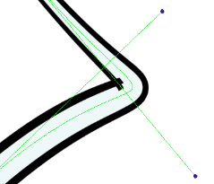
The AutoFold module is used to automatically fix the folding area of a deformer so no line overlap occurs. The AutoFold module is similar to the Fold module, but since it is automated it is optimized to fit the most standard folding point with fewer controls to set up.
This effect module is best used with Curve Deformers.
| 1. | In the Camera view, enable Render |
| 2. | In the Network view, navigate to the Deformation effect module which is causing the unwanted overlap. |
| 3. | In the Module Library, select an AutoFold module and drag it to the Network view. |
| 4. | Connect the AutoFold module directly under the Deformation effect module which is causing the unwanted line effect. |
| 5. | Click the square yellow button to open the AutoFold Layers Properties dialog box. This is where you can customize the AutoFold settings. |
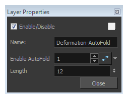
| 6. | In the Enable AutoFold field, type 1 to enable it or 0 to disable the effect. |
| 7. | In the Length field, set the length of the fold axis line. |
| 8. | Click Close. |
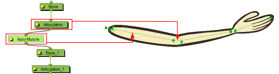
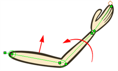
The Auto-Muscle module is used to simulate muscle movement. This will allow your characters to flex their muscles when they lift something or to create muscle-tone when they move. When the Auto-Muscle module is connected to a Bone Deformer that is rotated, the drawing is automatically inflated to simulate muscle movement in the limb.
How to use the Auto-Muscle module
| 1. | In the Network view, navigate inside the Deformation Group you want to add an Auto-Muscle effect to. |
| 2. | In the Module Library, select an Auto-Muscle module and drag it to the Network view. |
| 3. | Connect the Auto-Muscle module directly under the Articulation and after the Bone you want the effect to be applied to. |
| 4. | In the Network view, click on the Auto-Muscle module’s square yellow button to open the Layer Properties dialog box. |
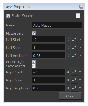
| 5. | You can set the following parameters in the Auto-Muscle Layer Properties dialog box: |
| Parameter | Description |
| Name | Use this field to rename the module. |
| Muscle Left |
This option is enabled by default. When enabled, the left side of the Bone Deformer will inflate as the articulation is rotated toward the direction of the Bone Deformer. Disable this option if you do not want the left side of the bone to inflate.
|
| Left Start |
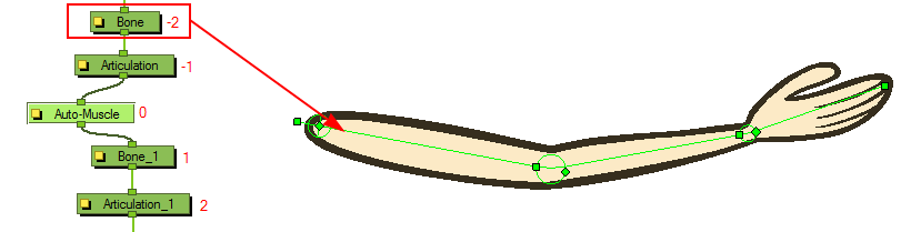
The default value of the starting position of the left-side muscle is set to -2. This means it will start at the deformer situated two steps before the position where the Auto-Muscle is connected. You can change the starting point by typing the number corresponding to the deformer module.
|
| Left Span | This parameter controls the length (muscle length) over which the effect module will be applied to the left side of the deformer. By default the setting is 1, representing the length of the deformer to which it is applied. |
| Left Amplitude |
This parameter controls the physical size of the left muscle. Increase the value to make the muscle bigger, decrease the value to make it smaller.
|
| Muscle Right |
This option is enabled by default. When enabled, the right side of the Bone Deformer will inflate as the articulation is rotated toward the direction of the Bone Deformer. Disable this option if you do not want the right side of the bone to inflate.
|
| Same as Left |
This option is enabled by default, allowing each side of the Bone Deformer to inflate to follow the rotation of the articulation. Enable this option to synchronize the right muscle with the left so both muscles will inflate when the articulation is rotated to the left.
|
| Right Start |
The default value of the starting position of the right-side muscle is set to -2. This means it will start at the deformer situated two steps before where the Auto-Muscle is connected, in this case, Bone. You can change the starting point by typing the number corresponding to the deformer module.
|
| Right Span | This parameter controls the length (muscle length) over which the effect module will be applied to the right side of the deformer. By default the setting is 1, representing the length of the deformer to which it is applied. |
| Right Amplitude | This parameter controls the physical size of the right muscle. Increase the value to make the muscle bigger, decrease the value to make it smaller. |
Just like a standard Composite module, the Deformation-Composite module is used to bring together all the elements that are connected to it, allowing you to customize parameters that will influence the result of the output.
The Deformation-Composite links the deformation chain to the graphic element to which it is related. This is automatically added to your Deformation Group when creating a deformer chain with the Rigging ![]() tool.
tool.
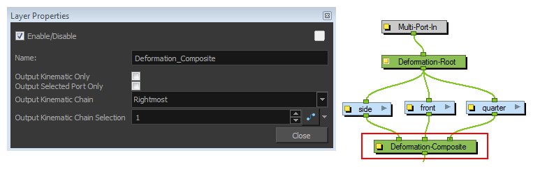
You can set up the following parameters in the Deformation-Composite Layer Properties window:
| Parameter | Description | ||||||
| Name | Use this field to rename the module. | ||||||
| Output Kinematic Only | This option is disabled by default, allowing the deformation chain to be output correctly. This option should be enabled in order to output the chain information position only. This will allow you to connect a part to the hierarchy without it undergoing the deformation applied to the rest of the chain—see Assembling the Parts | ||||||
| Output Selected Port Only |
This option is important if you have several deformation chains for one element, as in the case of a character with multiple poses.
|
||||||
| Output Kinematic Chain |
Lets you select a deformation chain option to use. This parameter is used when the Output Selected Port Only option is enabled.
|
||||||
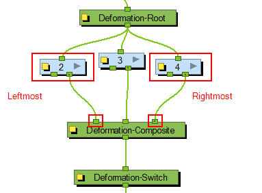
| Rightmost: Only the first chain connected to the right of the composite module will be used. | |||||||
| Leftmost: Only the first chain connected to the left of the composite module will be used. | |||||||
| Select: If you select this option, you can define which chain to output according to the order they are connected from left to right. | |||||||
| Use First Connected Element’s Exposure as Key: Allows the deformation effect to automatically detect which deformation chain to use (subgroup) by detecting the exposure of the first element connected to the deformation. This option is used in the case of a multiple pose rig—see Creating a Full Character Turnaround Deformation Rig | |||||||
| Use Parent Composite’s Connected Element Exposure: When the Output Kinematic Only option enabled, the information from the parent element’s exposure is used to attach the child to the correct chain, following which pose is exposed—see Assembling the Parts | |||||||
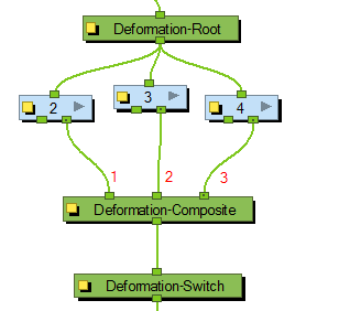
| Output Kinematic Chain Selection |
When the Output Selected Port Only option is selected AND the Select option is used as the Output Kinematic Chain setting, this field defines which deformation chain you want to use on your element. Select the number which corresponds to the left to right order that the chains are connected to the Deformation-Composite module.
You can attach this value to a function and enable different chains over a period of time on specific frames. This value can be modified in the Timeline view by using the Deformation-Switch layer. Since the Deformation-Composite module is only visible in the Network view, the layer has a reference to this parameter enabling you to easily edit the value when working in the Timeline view. Note: If you are working with Create Posed Deformer in Create Deformation Above/Under enabled, you will not need to set up this option. The settings in the Deformation-Composite module will automatically be set up and the system will recognize which chain to use following the element’s exposure—see Creating a Full Character Turnaround Deformation Rig |
The Deformation-Root is the starting point and pivot for the deformer chain. When you use the Rigging ![]() tool, this module is automatically added to the top of your deformation chain in the Deformation group.
tool, this module is automatically added to the top of your deformation chain in the Deformation group.
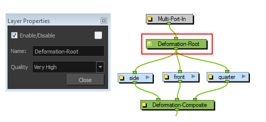
You can modify the quality level of the Deformation effect in the Deformation-Root Layer Properties window:
| Parameter | Description | |||||||||||||||
| Name | Use this field to rename the module. | |||||||||||||||
| Quality |
Defines the number of slices the graphic is split into and used when undergoing a deformation. The higher the quality level, the more slices are created and the smoother the deformation applied to the graphic. There are five levels of quality:
|
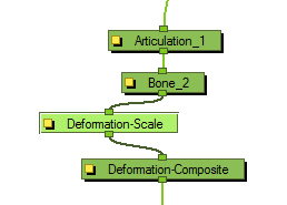
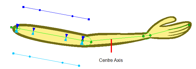
The deformers can only be scaled along the centre axis to adjust the length of the limb. The Deformation-Scale can be used in combination with a Bone or Curve deformer to scale a drawing so it follows the opposite direction of the deformer axis (the width). For example, when combined with function curves this can be used to create advanced muscle effects. All these settings can be animated over time.
How to set up the Deformation-Scale effect module
| 1. | In the Network view, navigate inside the Deformation Group to which you want to add a Deformation-Scale effect. |
| 2. | In the Module Library, select a Deformation-Scale module and drag it to the Network view. |
| 3. | Connect the Deformation-Scale module directly under the lower deformer module of your chain. |
| 4. | In the Network view, select the Deformation-Scale module and select View > Show > Control to display its controls in the Camera view. Refer to for more information about display options. |
| 5. | Click on the square yellow button of the Deformation-Scale module to open the Layer Properties window. |
| Parameter | Description |
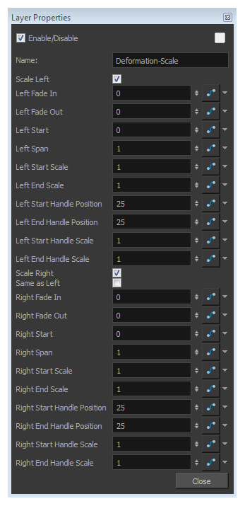
| Name | Use this field to rename the module. |
|
This series of options controls the left side scaling deformation. |
|
| Scale Left | This option is enabled by default. It allows the left side of the deformer to be scaled. In the Camera view, the dark blue controls are used for the left side. If you disable this option, the controls will be hidden and no scaling deformation will occur for this side. |
| Left Fade In | The value is set to 0 no fade, by default. Increase the value to add a fade effect to smooth the transition between the starting point of the scale and the area before it. |
| Left Fade Out | The value is set to 0 no fade, by default. Increase the value to add a fade effect to smooth the transition between the Left Span point of the scale and the area after it. |
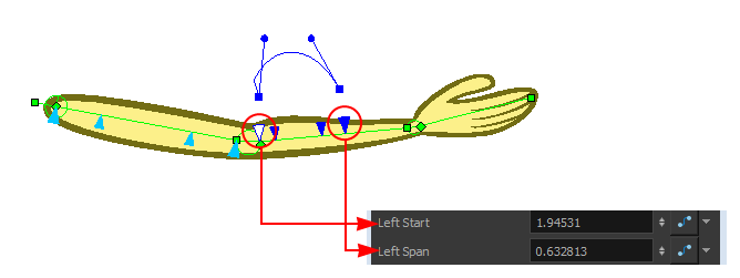
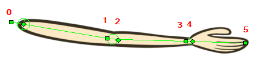
| Left Start | This parameter defines the starting point of the left scale deformation. The default value is 0 and represents the Deformation-Root. Each main control point count for +1. |
| Left Span | This parameter defines the length of the left scale effect. |
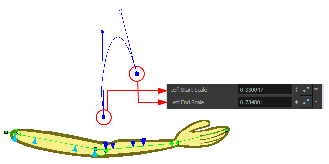
| Left Start Scale | This parameter definers the start of the left scale effect. |
| Left End Scale | This parameter definers the end of the left scale effect. |
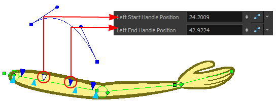
| Left Start Handle Position | This parameter definers the starting position of the left handle. |
| Left End Handle Position | This parameter definers the ending position of the left handle. |
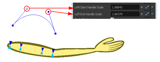
| Left Start Handle Scale | This parameter definers the starting position of the left scale handle. |
| Left End Handle Scale | This parameter definers the ending position of the left scale handle. |
| Scale Right | This option is enabled by default. It allows the right side of the deformer to be scaled. In the Camera view, the light blue controls are used for the right side. If you disable this option, the controls will be hidden and no scaling deformation will occur for this side. |
| Same as Left |
This option is disabled by default. It means that the left and right sides will use different scaling parameters. If you enable this option, the right side controls will be hidden in the Camera view and the left parameters will be used for both side for a symmetrical scaling effect. |
| The right side parameters are a mirror of the left side parameters | |
| 6. | In the Layer Properties dialog box, you can set up all the parameters. |
| 7. | In the Tools toolbar, select the Transform |
| 8. | In the Camera view, set up the Deformation-Scale module (you can also set these parameters directly in the Layer Properties window): |
| ‣ | To modify the scaling value of the curve, drag the two control handles away and forward from the deformation axis. |
| ‣ | Move the first blue arrow along the deformer’s central axis to set the starting point of the Deformation-Scale and the last arrow to set the length (span) of the transformation. |
| ‣ | Drag the square scaling curve control points away and forward from the deformer axis to set the scaling value at the starting and ending point. |
| ‣ | Drag the two middle blue arrows along the deformer’s centre axis to set the position of the curve handles. |
| 9. | You can animate the different parameters of the Deformation-Scale module by enabling the Animate |
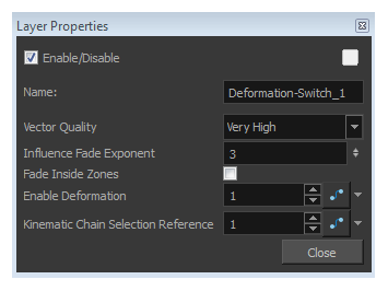
The Deformation-Switch module acts as a On and Off switch for the deformation chain. It is also the module which controls the Zone of Influence Fade area. The Deformation-Switch also displays a Kinematic Chain Selection Reference option, this allows you to modify the chain selection directly in the Timeline view.
| Parameter | Description | |||||||||||||||
| Name | Use this field to rename the module. | |||||||||||||||
| Vector Quality |
Defines the quality of the deformation effect when your drawings are stretched and deformed. There are five levels of quality:
|
|||||||||||||||
| Influence Fade Exponent |
A value of 1 is similar to a linear curve. A higher value will result in an ease-in type of curve. A lower value will result in an ease-out type of curve. |
|||||||||||||||
| Fade Inside Region | This option is disabled by default. Thefade effect will occur outside the zone of influence. Enable this option to have the fade effect inside the Zone of Influence—see Zones of Influence. | |||||||||||||||
| Enable Deformation | Acts as an on/off switch for the deformation. The value of this field is set to 1 by default, this means the deformation is enabled. Enter a value of 0 to disable it. | |||||||||||||||
| Kinematic Chain Selection Reference | Determines which chain is selected and used at a specific frame. It is a reference to the option in the Deformation-Composite module. Having this reference in the Deformation-Switch module allows you to use and modify the chain selection value directly in the Timeline view since the Deformation-Composite module is only visible in the Network view. |
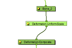
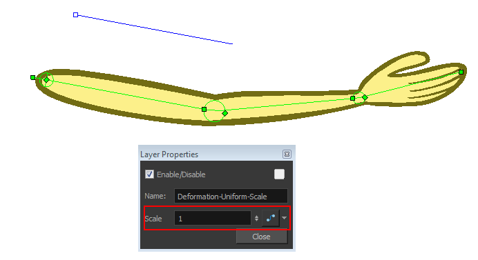
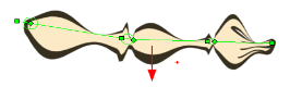
The Deformation-Uniform-Scale effect module is used to create the squash and stretch effect on your animated deformation rig. It will let you scale the rigged element on the opposite axis of the deformer (width).
How to use the Deformation-Uniform-Scale module
| 1. | In the Network view, navigate inside the Deformation group to which you want to add a Deformation-Uniform-Scale module. |
| 2. | In the Module Library, select the Deformation-Uniform-Scale module and drag it to the Network view. Note that the Deformation-Uniform-Scale module name changes to Deformation-Uniform-Scale as it enters the Network view. |
| 3. | Connect the Deformation-Uniform-Scale module directly below the lowest deformation module in your chain. |
| 4. | In the Network view, select the Deformation-Uniform-Scale module. |
| 5. | Display the Uniform Scale controls in the Camera view by pressing Shift + F11—see Displaying the Deformation Controls. |
| 6. | In the Camera view, drag the handle to resize the width of the limb. You can also use the Scale field to enter a specific value. These parameters can be animated over time. |
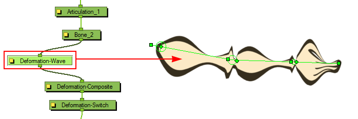
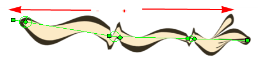
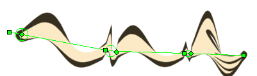
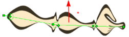
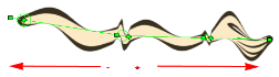
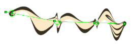
The Deformation-Wave effect deforms the chain by adjusting the scaling in a waveform style. It can be used to animate a wave deformation effect on your deformation chain over a period of time.
How to use the Deformation-Wave effect
| 1. | In the Network view, navigate inside the Deformation group to which you want to add a Deformation-Wave effect to. |
| 2. | In the Module Library, select an Deformation-Wave module and drag it to the Network view. Note that the Deformation-Wave module name changes to Deformation-Wave as it enters the Network view. |
| 3. | Connect the Deformation-Wave module to your deformation chain. |
A wave deformation is applied to the limb or art connected to the deformation chain.
| 4. | In the Network view, click on the Deformation-Wave module’s square yellow button to open the Layer Properties window. |
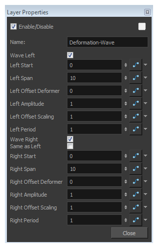
| 5. | You can set the following parameters in the Deformation-Wave Layer Properties window: |
| Parameter | Description |
| Name | Use this field to rename the module. |
| Wave Left | This option is enabled by default, allowing the Deformation-Wave effect to be applied on the left side of the deformer chain. Disable this option to prevent the effect from being applied. |
| Left Start | Defines the length of the left wave effect. |
| Left Span |
Defines the starting point of the left wave deformation. The default value is 0 and represents the Deformation-Root. Each main control point count for +1.
|
| Left Offset Deformer |
This is the parameter you may want to connect to a function. It controls the offset of the deformation on the left side and allows you to create a fluid wave animation along the deformer axis.
|
| Left Amplitude |
Controls the height of the left wave effect.
|
| Left Offset Scaling |
Used to apply an offset value to the amplitude of the left wave. The wave will be lifted and become higher, or dropped and become lower, depending whether the value is increased or decreased.
|
| Left Period |
Controls the interval of occurrence of the left waves. By default the value is 1, meaning that a wave will occur for every deformer. If you decrease the value to 0.5, it will result in a wave occurring every half deformer. |
| Wave Right |
By default this option is enabled, allowing the Deformation-Wave effect to be applied on the right side of the deformer chain. Disable this option to prevent the effect from being applied. |
| Same as Left |
This option is disabled by default. It allows the left and right size of the Deformation-Wave to be controlled separately. Select this option if you want the effect to be symmetrical and controlled by the left side parameters. |
| Right Start |
Defines the starting point of the right wave deformation. The default value is 0 and represents the Deformation-Root. Each main control point count for +1.
|
| Right Span |
Defines the length of the right wave effect. |
| Right Offset Deformer |
This is the parameter you might want to connect to a function. It controls the offset of the deformation on the right side, allowing you to create a fluid wave animation along the deformer axis.
|
| Right Amplitude |
Controls the height of the right wave effect.
|
| Right Offset Scaling |
Used to apply an offset value to the amplitude of the right wave. The wave will be lifted and become higher, or dropped and become lower, depending whether the value is increased or decreased.
|
| Right Period |
Controls the interval of occurrence of the right side waves. By default the value is 1, meaning that a wave will occur for every deformer. If you decrease the value at 0.5 it will result in a wave occurring every half deformer. |
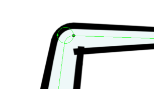
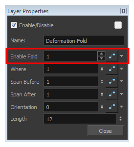
The Fold effect is used when bending a deformation further than the drawing is able to take it. This may result in an unwanted overlap of the line art at the junction of the articulation or deformation. The Fold effect lets you control certain parameters that will help eliminate the unwanted line effect.
| 1. | In the Camera view, enable the Render |
| 2. | In the Network view, navigate to the Deformation effect module causing the unwanted overlap (in this case, an articulation). |
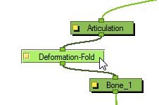
| 3. | In the Module Library, select the Fold module and drag it to the Network view. |
| 4. | Connect the Deformation-Fold module directly under the deformation effect module which is causing the unwanted line effect. |
| 5. | In the Network view, select the Deformation-Fold module and select View > Show > Control to display its controls in the Camera view. |
| 6. | In the Tools toolbar, select the Transform |
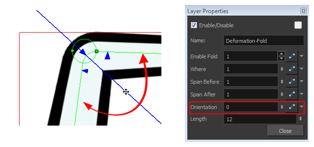
| 7. | In the Camera view, set up the Deformation-Fold. You can also set these parameters directly in the Deformation-Fold Layer Properties: |
| ‣ | Click on the fold axis and rotate it to match the angle of the bend articulation. |
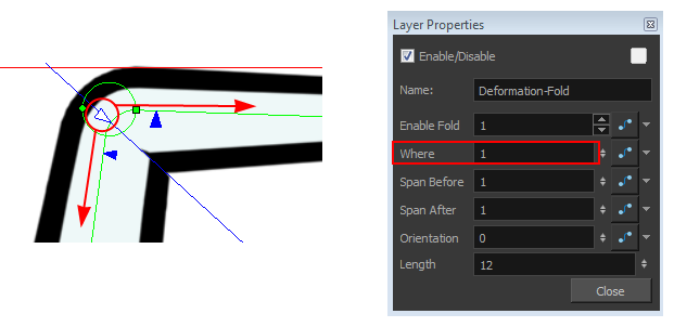
| ‣ | Use the middle arrow to position the axis along the deformer’s central line. It should be in the corner of the bending area. |
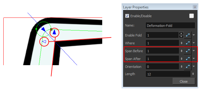
| ‣ | Use the right and left arrows to control the appearance of the two overlapping lines. |
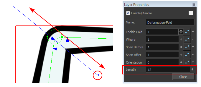
| ‣ | Use the axis’s square handle to lengthen or shorten the axis. |
| 8. | If your character moves a lot and you need to adjust the fold at different positions to follow the limb animation, you can set up the Deformation-Fold effect in a different position over time. To do this, enable the Animation |
| 9. | You can also enable and disable the Deformation-Fold effect over time by connecting a function to the Enable Fold parameter in the Layer Properties. A value of 1 enables the effect, a value of 0 disables the effect. |
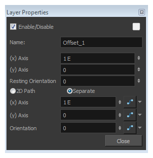
The Offset effect lets you position the root of your deformation chain. It is automatically added to your Deformation group when you create a deformation rig using the Rigging ![]() tool.
tool.
When you move your chain using Setup mode ![]() , the values at the top section of Layer Properties update to follow the new resting position. If you move the chain without being in the Setup mode, you will be able to animate the active position of the chain over time. In that case, the bottom values will be connected to functions.
, the values at the top section of Layer Properties update to follow the new resting position. If you move the chain without being in the Setup mode, you will be able to animate the active position of the chain over time. In that case, the bottom values will be connected to functions.
| Parameter | Description | ||||||
| Name | Use this field to rename the module. | ||||||
| (x) Axis |
Sets the resting position of the Deformation-Root on the X (east/west) axis. |
||||||
| (y)Axis |
Sets the resting position of the Deformation-Root on the Y (north/south) axis. |
||||||
| RestingOrientation |
Sets the rotation angle of the resting position of the Deformation-Root. |
||||||
| Type |
Lets you choose the type of coordinates to use:
|
||||||
|
(x) Axis (y) Axis |
This option is only available when the Type is set to Separate. It is used to set the active position value of the Deformation-Root on the X (east/west) and Y (north/south) axis. You can enter the value, use the up and down arrow buttons to choose a value, or use the Transform |
||||||
| Path | This option is only available when the Type is set to 2D Path. It is used to set the active position value of both Y and X axis. Use the Transform |
||||||
| Orientation | Sets the rotation angle of the active position of the Deformation-Root. You can enter the angle, use the up and down arrow buttons to choose the desired value, or use the Transform |