Assembling the Parts
After you have created all the deformation chains for your character, you will need to assemble these separate body parts into a puppet.
To avoid problems such as having the head stretched by the neck deformers or a hand modified by the neck and body deformers, it is recommended to put them on a separate layer. When they are on a separate layer, rig them using a Kinematic output coming directly from your Deformation group, instead of the normal hierarchy connection between modules. This will let you connect a part directly to it, so it will only be influenced by the position of its parent and not undergo any deformation. This is recommended as a method of optimizing the functionality of the puppet and also as a way of avoiding any unwanted distortion effects for any assembled parts.
| 1. | In the Network view, locate the puppet’s head. You can also select the head in the Camera view using the Transform tool and then press O in the Network view to center your selection. |
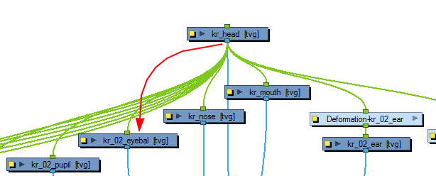
| 2. | If you did not add a Deformation effect to this module, you can connect all the facial feature modules as its children, just as you would normally do with a typical cut-out character rig. |
| 1. | In the Network view, locate the body of the puppet. Select the Deformation group linked to the character’s body module. |
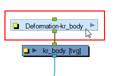
| 2. | In the Deformation toolbar, click the Create Kinematic Output |
A Deformation-Composite module is added inside your Deformation group. This is set up to create a special output which you can use to connect your modules and create the puppet’s hierarchy. It also automatically creates the necessary connections, so that every pose is part of the setup. The deformation will not influence the modules that are connected to this output.
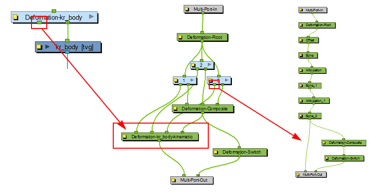
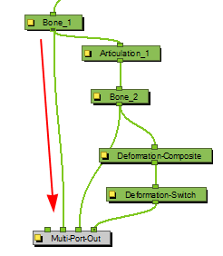
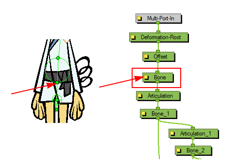
By default, the last deformer module of each deformation chain is connected to this new Deformation-Composite. The extremity of this deformer is where the child element will be attached. In this case, the last bone is the neck.
| 3. | As there will be several parts connected to this body Deformation group, you should rename the new Composite modulewith a relevant name. Click on the module’s yellow square button to display the Deformation-Composite module’s properties. |
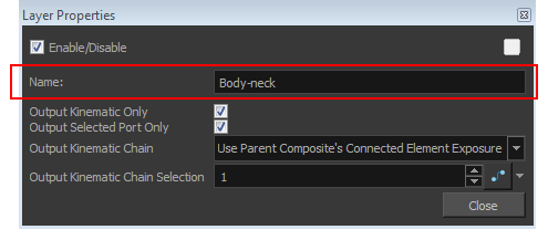
| 4. | In the Name field, type a new name for the module and click Close. |
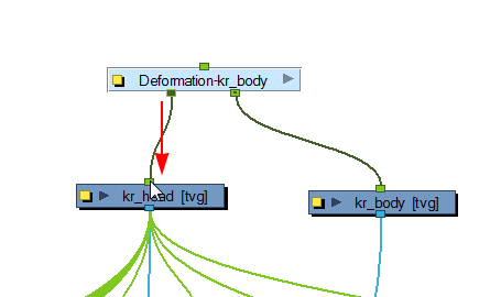
| 5. | In the Network view, exit the Deformation group and go back to Top level. |
| 6. | Connect the new bottom port of the body Deformation group module into the top port of the head module. |
| 7. | In the Network view, select the body Deformation group module again and click the Create Kinematic Output |
| 8. | Enter the Deformation group and rename the newly created Deformation-Composite module. In this example: body-shoulder. |
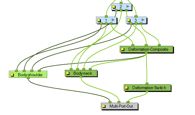
By default, the last deformer of each subgroup is linked to this new Deformation-Composite module. In this case, this Composite will act as the shoulder attachment for the two arms. If the connections are left as is, the arms will follow the movements of the neck and head. For this reason, it is important to select the correct Bone or Articulation.
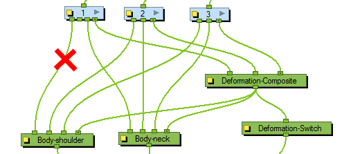
| 9. | In the Network view, enter the first deformation subgroup. |
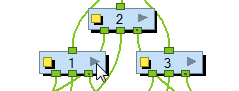
| 10. | Inside the first subgroup, locate the connection to break. |
In this example, we need to break the connection to the Body-shoulder module. Click on the node and pull out the cable to disconnect it.
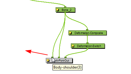
Notice that the disconnected node will still be visible on the Multi-Port-Out module. This is because a cable is still connected to the output port outside of the subgroup. This will be removed at a later step.
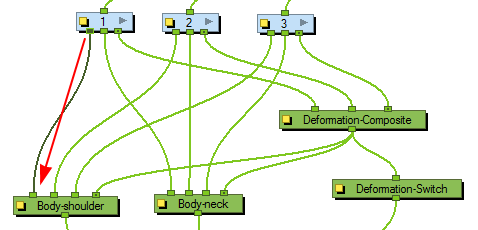
| 11. | Locate the Bone |
| 12. | Click on the desired deformer module bottom node and drag the cable to the Multi-Port-Out module to create a connection. |
| 13. | Exit the subgroup and go back to the body Deformation group. |
| 14. | Disconnect the current unused connection between your first subgroup and the shoulder Deformation-Composite module. This will also remove the empty node on the Multi-Port-Out module inside your subgroup. |
| 15. | Connect the remaining bottom node of your subgroup to the shoulder Deformation-Composite module. |
| 16. | Repeat steps 9 to 15 for each subgroup contained in your body Deformation Group. |
| 17. | In the Network view, go back to the Top level. |
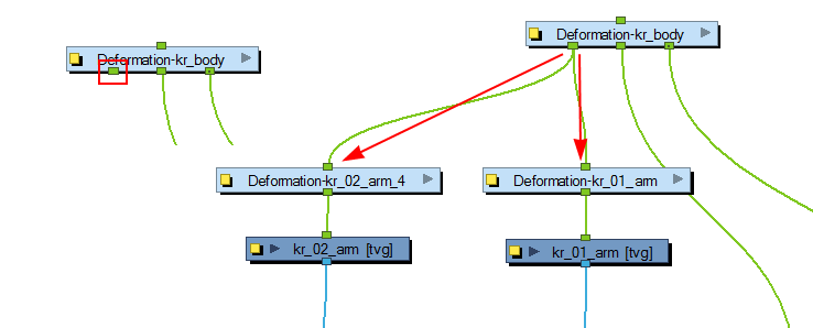
| 18. | Connect the two arms to the available bottom node of the body Deformation group. |
| 19. | Repeat steps 7 to 18 for the legs and any other parts that need to be assembled. Remember to link the deformer modules used for the hips to the Kinematic Output. |
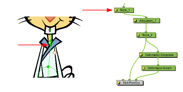
When you have completed this process the body Deformation group should look similar to this.
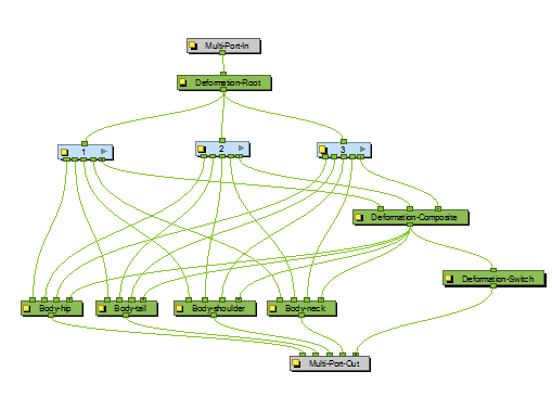
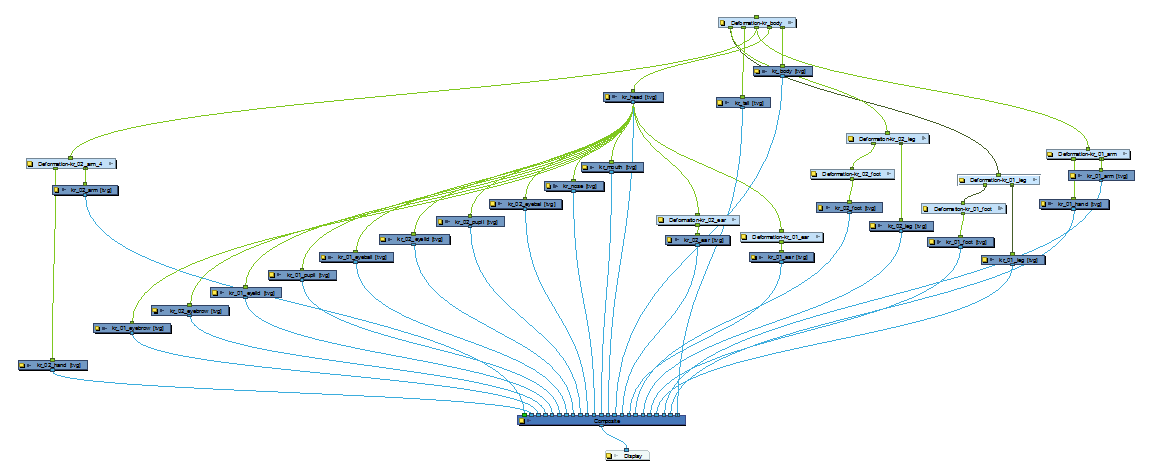
And the final network should look similar to this.