


Zones of Influence
To increase the quality of your animation and the accuracy of the Deformation effect, you can modify the zones of influence around the deformation chains. A zone of influence is the area around the deformer within which art will be influenced by the deformation. The deformer has the power to shape all art contained within the influence area on its own element or on its children elements.
Zones of influence are different depending on the deformer type and zone type you selected.
You can find the settings for the zones of influence in the layer properties of the
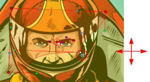
When working on a cut-out puppet built on several element layers, the best choice is to keep the default Infinite option as the zone of influence type. In the following examples, the zones of influence are explained through deformation chains on a single bitmap image. The image was previously imported and vectorized with colour.
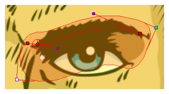
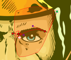
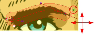
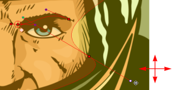
When you set up the shape of your Elliptic zone of influence, you should be as accurate as possible and make sure that only the element that you want to follow the deformation is included inside the zone.
When you have an Elliptic zone of influence selected in the Network view, you can convert it to a Shaped zone using the Convert Elliptic Zone of Influence to Shape option.
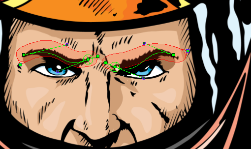
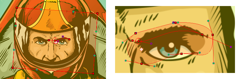
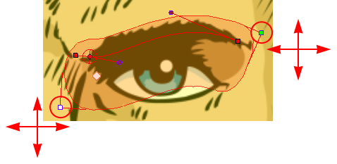
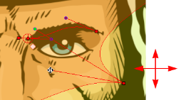
When you set up the boundaries of your Shaped zone of influence, you should be as accurate as possible and make sure that only the elements that you want to follow the deformation are included inside the zone.
To better illustrate the zone of influence Fade Radius and its effect, the bitmap picture will be swapped with a grid pattern.
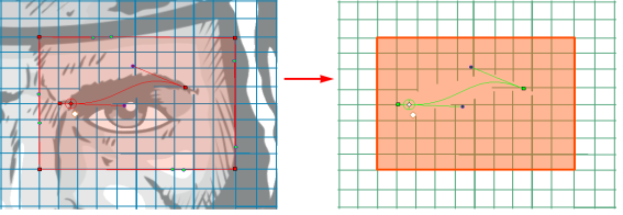
There is an area called the deformer Fade which surrounds the zone of influence; this is the link between the strict boundaries of the zone of influence and the surrounding region. This area gradually stretches or squashes following the deformation. You can edit the Fade Radius value to modify the size of this area and the exponent of the deformation fade effect.
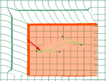
You can change the default behaviour so the fading effect is inside the zone of influenceinstead of outside. This is explained in this example.
| 1. | In the Deformation toolbar, enable the Setup Mode |
| 2. | Once you have created a Bone and Articulation or Curve deformation chain, in the Network view, navigate to your deformer module, inside the element’s Deformation Group and inside the pose subgroup if applicable. |
| 3. | Click on the deformer module’s square yellow button to open the Layer Properties dialog box. |
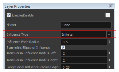
| 4. | In the deformer Layer Properties, select the type of Zone of Influence you want from the Influence Type menu. |
| Parameter | Description |
| Zero Influence | The Zone of Influence does not exist. No deformation will happen. |
| Infinite Influence | The default and most commonly used zone of influence. The Zone of Influence has no boundary and covers the whole element to which the deformer is linked to and its children, excluding areas that are already part of another elliptic or shaped zone of influence. The Infinite influence zone will from the centre of your skeleton, going towards infinity, working in perpendicular with the skeleton. This is the recommended Zone type for a cut-out puppet assembled from several element layers. |
| Elliptic Influence |
The zone of influence boundary is defined by an elliptical shape whose size can be customized using the Bone, Articulation
|
| Shaped Influence |
The zone of influence boundary is defined by a shape which you can customize using the Transform
|
| 5. | When you select the Elliptic or Shaped type, the zone of influence appears in the Camera view where you can customize the shape using the Transform tool and Layer Properties options. |
| 1. | In the Deformation toolbar, enable the Setup Mode |
| 2. | In the Tools toolbar, select the Transform |
| 3. | In the Network view, select the deformer’s module to which you want to customize the Elliptic Zone of Influence. |
| 4. | Click on the deformer module’s square yellow button to open the Layer Properties dialog box. |
| 5. | In the deformer Layer Properties, setup the ellipse shape by adding values to the various fields: |
| Parameter | Description |
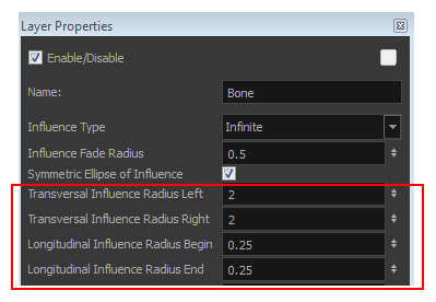
| Symmetric Ellipse Influence | Enabled by default. The shape of the ellipse will be symmetrical on both the transversal and longitudinal radii. In this case, use the Transversal Influence Radius Left field to set the transversal radius value and use the Longitudinal Influence Radius End field to set the longitudinal radius value. The two other fields will remain unused, unless you disable the Symmetric Ellipse Influence option. In that case, you can set up different radii sizes for the four radii directions. |
| Transversal Influence Radius Left |
When the Symmetric Ellipse of Influence option is enabled, this field controls both Left and Right transversal radius values. When disabled, it controls the size of the left transversal radius. By default this value is set to 2.
|
| Transversal Influence Radius Right |
When the Symmetric Ellipse of Influence option is enabled, this field loses its influence. The Left Transversal radius value is automatically applied to the Right Transversal. When this option is disabled, it controls the size of the Right Transversal radius. By default this value is set to 2.
|
| Longitudinal Influence Radius Begin |
When the Symmetric Ellipse of Influence option is enabled, this field loses its influence. The End Longitudinal value is automatically applied to the Begin Longitudinal. When this option is disabled, it controls the size of the Begin Longitudinal radius. By default this value is set to 0.25.
|
| Longitudinal Influence Radius End |
When the Symmetric Ellipse of Influence option is enabled, this field controls both the Begin and End Longitudinal radius values. When this option is disabled, it controls the size of the End Longitudinal radius. By default this value is set to 0.25.
|
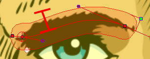
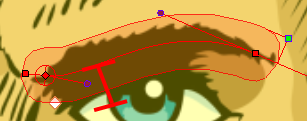
| 6. | You can also modify the elliptic shape in the Camera view, using the Transform |
| ‣ | If the Symmetric Ellipse of Influence option is enabled, one control point will be available in the Camera view. Drag this point in any direction to increase or decrease the size of the Zone. Dragging it left/right will modify both longitudinal radius sizes. Dragging it up/down will modify both transversal radius sizes. |
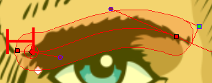
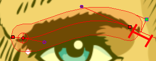
| ‣ | If the Symmetric Ellipse of Influence is disabled, two control points will be available in the Camera view. Drag the top-corner point left/right to modify the end longitudinal radius size and up/down to modify the left transversal radius size. Drag the bottom-corner control point left/right to modify the beginning longitudinal radius size and up/down to modify the right transversal radius size. |
| 1. | In the Deformation toolbar, enable the Setup Mode |
| 2. | In the Network view, select the deformer module that has an elliptic zone of influence type. |
| 3. | In the Deformation toolbar or Rigging Tool Properties, click the Convert Elliptic Zone of Influence to Shape |
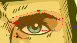
The zone of influence will automatically be converted to a shape. It will keep the shape it was when the button was pressed except, control points will appear all around the zone to allow the shape to be customized.
| 1. | In the Deformation toolbar, enable the Setup Mode |
| 2. | In the Tools toolbar, select the Transform |
| 3. | In the Network view, select the deformer module in which you want to customize the Shaped zone of influence . |
If you selected the Shaped option in the Layer Properties dialog box or in the Rigging tool properties, the zone of influence will be square. This square has control points on all four corners and each control point as two control levers. If you converted an Elliptic zone to a shape, the zone will have more control points and handles.

| ‣ | Click and drag a control point to redefine its position and shape. |
| ‣ | Click and drag the control lever handle to modify the corners and redefine the shape. |
| ‣ | Hold Alt down while dragging the control lever handle to move one handle at a time. |
| 1. | In the Network view, select the deformer module you want to modify. Note that this deformer needs to have an Elliptic or Shaped zone of influence type. |
| 2. | Click on the yellow square button of the module to open the Layer Properties dialog box. |
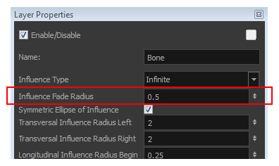
| 3. | Adjust the Influence Fade Radius field to modify size of the fading area. The default value is 0.5. |
| 4. | Click Close. |
| 5. | In the Network view, locate the Deformation-Switch module under the Deformation-Composite module in your deformation chain. |
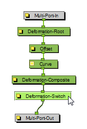
| 6. | Click on the yellow square button on the Deformation-Switch module to open the Layer Properties dialog box. |
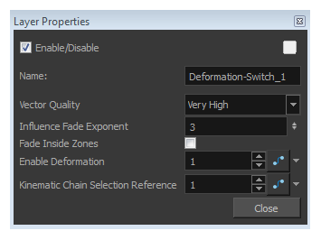
| 7. | In the Layer Properties dialog box: |
| Parameter | Description | |||||||||
| Influence Fade Exponent | Use the up and down arrow to modify the exponent value or type the exact value in the field.
|
|||||||||
| Fade Inside Region | By default this option is disabled, meaning that the Fade effect will occur outside of the Zone of Influence. You can enable this option so that the fade effect is inside the Zone of Influence. |