Like the Stage view, the Camera view allows you to see and position elements in your scene. However, contrary to the Stage view, the Camera view always displays elements from the point of view of the camera lens.
The difference is only visible when working on a 3D scene. If your scene contains 3D models or elements that are positioned at different depths in the stage, panning, zooming and rotating the Stage view will make elements appear in different positions relative to each other, whereas the Camera view will always display elements in the position and proportions they are meant to appear from the camera's point of view, and hence, the way they're mean to appear in the storyboard. This remains true even if you pan, zoom or rotate the Camera view. Furthermore, while the Stage view can be rotated on all axes, allowing you see your stage in perspective, the Camera view can only be rotated in 2D.
Hence, if you work in 2D, the Camera view is not useful. However, if you work in 3D, it is important to become familiar with the difference between both views and to use the Stage view when you want to position elements or the camera relative to each other in the 3D space, and the Camera view when you need to see elements in your stage as they will appear in the exported storyboard, or to position elements relative to the camera's point of view.

- In a view area, click the Add View
 button and select Camera.
| Tool Name | Icon | Description |
|
Grid |
|
Displays a grid in the Stage and Camera views. The default size is the standard 12-field animation grid, but you can choose another. You can also select View > Grid > Show Grid or press Ctrl + G (Windows) or ⌘ + G (macOS) |
|
Action Safe Area |
|
Displays the Title Safe Area frame inside the camera frame. By default, this area is 20% smaller than the camera frame. It is used as a guideline of the area that CRT displays might crop out of the picture. Visual elements such as text and logos should be placed within this area. NOTE The size of this area can be changed in the Camera tab of the Preferences dialog
|
|
Action Safe Area Mask |
|
Displays a semi-transparent black mask covering the area between the camera frame and the Title Safe Area frame. NOTE You can select the Action Safe Area Mask option by clicking and holding the Action Safe Area
|
| Title Safe Area |
|
Displays the Action Safe Area frame inside the camera frame. By default, this area is 10% smaller than the camera frame. It is used as a guideline of the area that CRT displays might crop out of the picture. Characters and action should be placed within this area. NOTE The size of this area can be changed in the Camera tab of the Preferences dialog
|
|
Title Safe Area Mask |
|
Displays a semi-transparent black mask covering the area between the camera frame and the Action Safe Area. NOTE You can select the Title Safe Area Mask option by clicking and holding the Title Safe Area
|
|
4:3 Safety |
|
Shows or hides the TV safety zone and the centre of the camera frame for a regular 4:3 resolution. If you are working on a widescreen project, for example, you can easily plan in advance the conversion of your project to a TV format. This way, you can create your project to fit both resolutions. You can also select View > Extras > Show 4:3 Safe Area. |
|
4:3 Area |
|
Shows or hides the 4:3 resolution zone without the centre of the camera frame and TV safety zone. You can also select View > Extras > Show 4:3 Area. |
|
Camera Mask |
|
Shows or hides a black mask around the scene’s frame to avoid seeing anything outside the Camera frame. This is handy when you are setting up the scene as it allows you to see the scene’s composition better. You can also select View > Extras > Camera Mask. |
| Show Alignment Guides |
|
When enabled, alignment guides will be visible in the Stage View and the Camera View. This is enabled by default. Disabling this option will hide and disable alignment guides, meaning that animation and drawing tools will not snap to them, even if the |
| Show Overlays |
|
Displays information about the current frame and panel in the Stage and Camera views, over the artwork. By default, this displays the timecode of the current frame, as well as the name of the current scene and of the current panel. You can configure what to display in the overlays by double-clicking or long-clicking on this button and selecting |
|
Reset View |
|
Resets any panning, zooming or rotation done in the Stage view and returns the display to its initial settings. You can also select View > Reset View or press Shift + M. NOTE This option works with the Camera View.
|
|
Reset Rotation |
|
Resets any rotation done in the Stage or Camera view and returns the display to its initial rotation settings. You can also select View > Reset Rotation or press Shift + X. |
|
Zoom Factor |
- |
Lets you enlarge or reduce the Stage or Camera view display. If you want the camera frame size to always match the size of your Stage view, select the Fit to View option. |
|
Layer Name |
- |
Displays the name of the selected layer of the current panel. |
|
Tool Name |
- |
Displays the name of the selected tool. If you override a tool using an overriding keyboard shortcut, the tool’s name turns red |
|
Colour Picker |
|
Displays the currently selected colour in the Colour View . You can click the colour swatch to open the Colour view and select a new colour. |
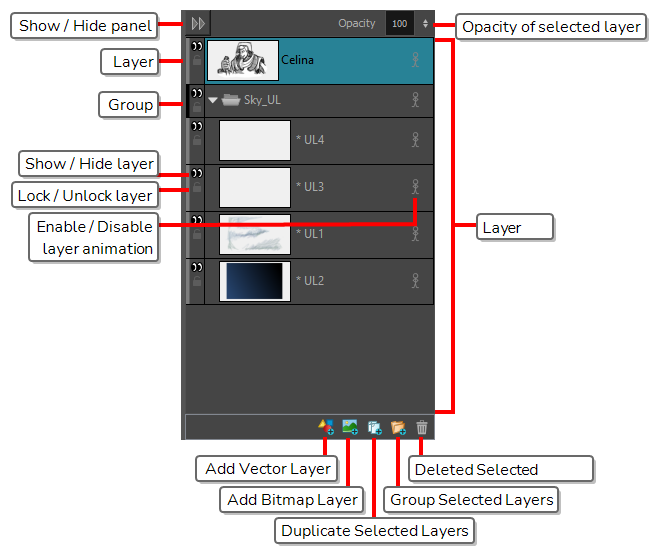
| Layer Panel | - |
The Layer panel is where a scene’s layers are superposed to form the final image. When you import an image or draw in a panel, you are actually adding artwork to one of its layers. By default, each panel has two layers; a background layer (BG) and a foreground layer (A). As you add layers, they are automatically assigned subsequent letters in alphabetical order, but you can rename them. They are also placed on top of the selected layer or at the very top of other layers if there is no layer selected in the panel. |
|
Add Vector Layer |
|
Adds a vector layer to the Layers list. |
|
Add Bitmap Layer |
|
Adds a bitmap layer to the Layers list. |
|
Duplicate Selected Layers |
|
Duplicates selected layers so you can quickly copy and paste in one operation. Unlike copying a layer, you cannot paste multiple copies of a layer on other panels. Duplicating layers is only available within one panel. Duplicated layers retain their names and are appended with a number. |
|
Group Selected Layers |
|
Groups selected layers. The grouped layer is named Group and appended with an underscore and a number. For example, Group_1. Each time you creat a group, the number is incremented. |
|
Delete Selected Layers |
|
Deletes the selected layers. |
