3D Layer Modes

In the Layers view, there are three different modes that can be applied to affect 3D objects in a Storyboard Pro scene. You can revert a flattened 3D object back to its 3D state, flatten a 3D object or render a bitmap drawing of your 3D object.
For more information on the Layer window, see Viewing the List of Layers.
![]()
The three 3D Layer mode options are the following:
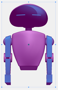
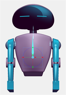
3D Mode 
3D mode will convert your flattened asset back into a 3D object. You will be able to transform your 3D model with the 3D manipulator in 3D space.
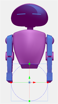
Layers created while in this mode, will appear in 3D space. The depth of the layers in the scene will be dependent on the plane they were created on. To affect the depth of surrounding layers, you will need to use the Top or Side view.
For more information about the Top and Side View windows, see Top View and Side View.
In this mode, the 3D model will be rendered based on its depth to the camera and will be subject to parallax with other layers and models in the scene.
This mode offers full access and control of your 3D models. However, this is also a heavier option. Storyboard Pro will process all of the information stored in the 3D model and render your 3D objects as they are posed.
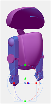
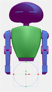
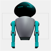
Flatten Mode 
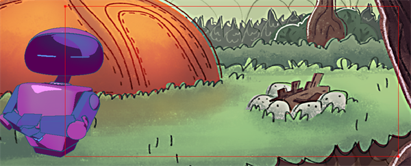
Flatten Mode will flatten a 3D object into a 2D card. When you opt to Stay in 2D, your 3D objects will automatically be flattened and put into this mode.
In this mode, the layers will be composited with respect to the layer order. The scene will not be subjected to parallax as all the elements will appear flat and be at the same depth. When applying transformations to the flattened 3D model, a bounding box will be provided rather than a 3D manipulator.
Though the 3D object is flattened, it retains its subnode information. This means that while in a 2D scene, there is a way to
-
Hold Ctrl while clicking your 3D object.
A 3D manipulator will appear over the whole 3D object.
-
While your object is in 3D mode, Click + Ctrl to select specific subnodes.
This is an optional step to select a specific subnode within your 3D structure.
Any 3D manipulations made will flatten with the changes applied.
Another method to manipulate a 3D object in 2D space is to use the Manipulate 3D Transform in Flattened Mode action.
-
In the Layers View, select
 Manipulate 3D Transform in Flattened Mode.
 -
Hold Ctrl while clicking your 3D object.
A 3D manipulator will appear over the whole 3D object.
-
While your object is in 3D mode, Click + Ctrl to select specific subnodes.
This is an optional step to select a specific subnode within your 3D structure.
-
When all deformations have been applied deselect Manipulate 3D Transform in Flattened Mode.
Any manipulations made will flatten with the changes applied.
By maintaining the parameters of a 2D scene, Storyboard Pro will be less heavy. This mode has the benefit of not weighing down the scene and maintaining the ability to make adjustments to your 3D objects.
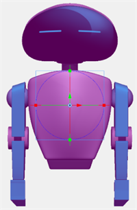
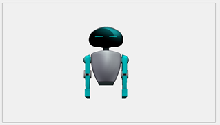
Bitmap Mode 
Bitmap Mode will convert a 3D object into a 2D bitmap drawing. When this mode is selected, the 3D object will be flattened and cropped to fit within the boundary of the camera.
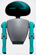
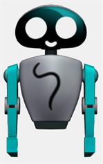
This mode is the lightest mode of all the 3D Layer modes. Due to the 3D object being flattened and converted to a bitmap drawing, Storyboard Pro is able to render quicker as it is only reading a flat 2D bitmap image with no 3D information.
3D Layer Actions
Next to the 3D Layer modes are 3D Layer actions. These actions will apply an action onto the selected 3D Model layers. You can render a bitmap image, allow 3D manipulation of a flattened model, fit the model to the current camera’s view and adjust the 3D Layer’s settings.
There are four 3D Layer actions. They are the following:
-
Render to Bitmap.
-
Manipulate 3D Transform in Flatten Mode.
-
Move to Fit Camera.
-
3D Layer Options.
Render to Bitmap 
Render to Bitmap will capture a render of the 3D object and will convert it into a bitmap drawing in your scene.
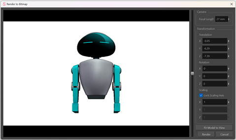
When this action is selected a Render to Bitmap window will open. In the Render to Bitmap window, you will be able to modify the position of the object in the scene, the proximity to the camera as well as scale and rotate the model.
Once you hit render, your 3D model will appear in the scene as a bitmap drawing.
If your 3D object is larger than the camera’s view, the 3D model will be cropped to fit the scene’s resolution. This box will only affect 3D objects and not any 2D elements.
There are three ways that Render to Bitmap can be applied. They can be applied by:
-
Clicking the action icon.
-
Render to Layer.
-
3D Effects.
-
Select the 3D Layer.
-
Click the
Render to Bitmap icon in the Layer view. -
Make adjustments in the Render to Bitmap window.
-
Click Render.
After clicking render, a bitmap image will appear in the selected layer.
-
In the Library window, Right + Click the 3D object.
-
Select Render to Layer.
-
Make adjustments in the Render to Bitmap window.
-
Click Render.
After clincking render, a bitmap image will appear in the new layer.
-
Right + Click 3D Layer.
-
Select 3D Effects > Render to Bitmap from the dropdown menu.
-
Make adjustments in the Render to Bitmap window.
-
Click Render.
After clicking render, a bitmap image will appear in the selected layer.
This will allow you to import your 3D object as a flat bitmap image in the scene.
Manipulate 3D Transform in Flattened Mode
Manipulate 3D Transform in Flatten Mode allows you to manipulate a 3D object in a 2D scene. When this action is active, any flattened 3D objects will be manipulatable in 3D space. It also allows for the 3D model to be transformed in 3D space relative to the camera; the 3D model when transformed in this state will be subject to parallax offset.
This option allows you to make adjustments to your 3D object without upgrading to a 3D scene. By remaining in a 2D scene the 3D model can be easily sorted with other 2D drawings and it can be transformed in a 2D context.
-
Activate Manipulate 3D Transform in Flattened Mode.
-
Hold Ctrl while clicking your 3D object.
A 3D manipulator will appear over the whole 3D object.
-
While your object is in 3D mode, Click + Ctrl to select specific subnodes.
This is an optional step to select a specific subnode within your 3D structure.
-
When all deformations have been applied deselect Manipulate 3D Transform in Flattened Mode.
Any manipulations made will flatten with the changes applied.
NOTE The ability to select and manipulate 3D objects in a 2D space will remain active as long as the Manipulate 3D Transform in Flattened Mode is engaged.
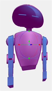
Move to Fit Camera View 
Move to Fit Camera View will reposition a 3D Layer to fit within the boundaries of the Camera View.
This action is best used with large environments or if a 3D object import is too large for the Camera view.
3D Layer Options 
The 3D Layer Options is a settings window that allows you to adjust the camera options for the 3D Layer.
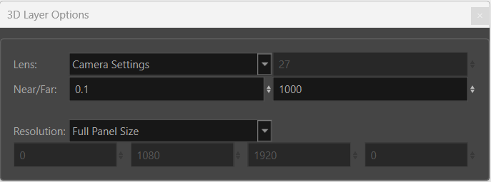
You are able to adjust the type and size of the camera lens, control the clipping planes of the camera and modify the bitmap’s cropping position and resolution size.
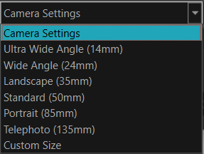
Lens
The Lens option dictates the focal length that will capture the 3D object in the Camera view. The Focal Length is a photography term that describes the size of the lens and its focal distance used when capturing the image of the scene.
A smaller focal length will provide a wider field of view, making the subject appear further and fitting more into the frame (wide angle lenses).
A larger focal length will provide a more narrow field of view, making the subjects appear closer.
The drop down menu allows you to select the focal length distance in millimetres that you want to capture your scene with.
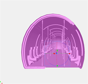
Near/Far
Near/Far is an attribute that allows you to change the clipping planes used when rendering the 3D model in the camera. The clipping planes define the depth at which the 3D rendering will begin and end, effectively cropping the rendered image within a certain depth range. By cropping your asset in Z-depth, you can control the portions of the model that will be visible at render, based on its relative depth in the view.
This allows you to remove elements in either or both the foreground and the background.
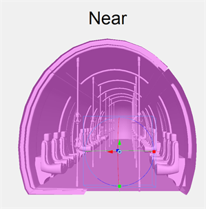
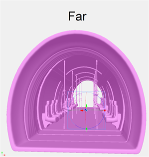
This option is most useful when your 3D object is not split into subnodes. While a subnode can be deactivated, if the entire 3D object is one large piece of geometry, the Near/Far clipping planes can be used to crop portions of the rendered image.

The attributes by default are set to 0.1 and 1000. The left dialog box will control the foreground clipping. The right dialog box will control the background clipping.
The far clipping plane can be used to modify the point at which the render ends. This value can be increased or decreased to allow for more or less of the model to be rendered in depth.
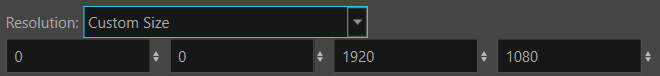
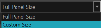
Resolution Panel Size
Resolution Panel Size dictates the cropping position and resolution of the bitmap when converting a 3D model to bitmap. In the dropdown menu, you have the option to set the resolution to Full Panel Size or Custom Size.
Full Panel Size will match the resolution of the scene. Converting a 3D model to bitmap will match the panel’s current position and resolution.

Custom Size allows you to set a custom position and resolution for the bitmap when converting a 3D model to bitmap.
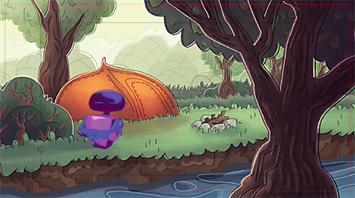
When the Custom Size attributes boxes are selected, a red bounding box will appear in the Camera and Stage view to show the scale that has been input.
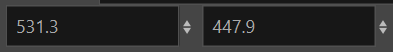
The custom size is defined by a starting position in the top left corner, and an ending position in the bottom right corner for the cropping.
The two dialog options on the left define the position at which the cropping begins in X, Y coordinates. The two dialog options on the right define the position at which the cropping ends in X, Y coordinates.
There are two ways to create a Custom Size. You can set the Custom Size by either:
-
Entering the numerical values. See Create a Custom Size by Entering Numerical Values.
-
Creating a bounding box. See Creating a Custom Size by Creating a Bounding Box.
-
In the Layers panel of the Stage or Camera view, select the 3D layer.
-
In the Layers View, select
3D Layer Options. The 3D Layer Options dialog box opens. -
In the Resolution dropdown, change Full Panel Size to Custom Size.

-
Enter the position to begin and end the cropping in the dialog boxes.
-
Click
Bitmap Mode.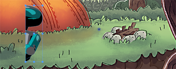
Upon hitting Bitmap Mode, the 3D Layer will be converted to a bitmap drawing and crop to fit within the specified dimensions.
-
In the Layers panel of the Stage or Camera view, select the 3D layer.
-
In the Layers View, select 3D Layer Options. The 3D Layer Options dialog box opens.
-
In the Resolution dropdown, change Full Panel Size to Custom Size.
-
Click one of the custom parameters box.
-
In Camera view, click and drag to define the cropping position and scale.
The initial click will define the starting point of the crop, dragging and releasing will define the ending point.
-
Click
Bitmap Mode.
Upon hitting Bitmap Mode, the 3D Layer will be converted to a bitmap drawing and crop to fit within the specified dimensions.