Shape-Aware Deformation Node
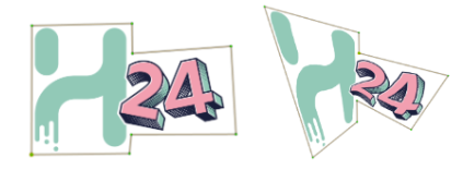
The Shape-Aware Deformation Node allows you to apply deformations to a drawing that respect the integrity of the overall drawing shape by localizing deformations to single deformation points.
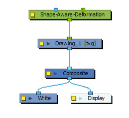
Connection
The following image is an example of a network connection for the Shape-Aware Deformation Node.
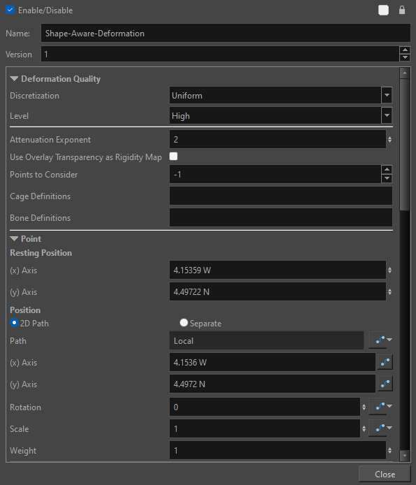
Properties
| Parameter | Description |
|---|---|
|
Deformation Quality |
|
|
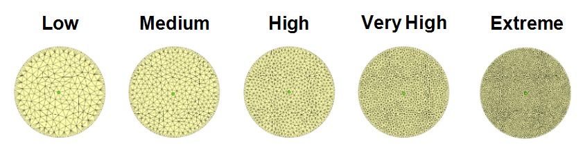
Level |
Corresponds to the density of the Deformation Mesh geometry. The drop down menu offers the option of Low, Medium, High, Very High and Extreme.
By default, the mesh is set to High. The lower the setting the less information there is in the geometry of the mesh. Conversely, the higher the level, the more geometric information there is in the mesh. NOTE The lower settings have less points generated and are best for more basic, geometric or polygonal shapes and the higher settings are best when deforming more organic or complex shapes and require more accuracy.
|
|
Attenuation Exponent |
Addresses the global sensitivity of the Shape-Aware Deformer. The value of the exponent will indicate how much weight a coordinate has in relation to the other coordinates. By default, the Attenuation Exponent is set to 2. NOTE
For best results, it is ideal to keep the value between 1.5 and 2.5. The higher the value, the larger the area of influence which will offer more rigidity.
|
|
Use Overlay Transparency as Rigidity Map |
When selected, anything drawn in the overlay layer impacts the Deformation Mesh and applies rigidity to the mesh structure. The opacity of the drawing in the overlay layer impacts the force applied on the mesh. The more transparent, the less the overlay drawing impacts the deformation resulting in less stiffness. The more opaque, the more the overlay drawing impacts the deformation resulting in more stiffness. |
|
Points to Consider |
Defines the strength and influence of the points scattered across the mesh. By default the Points to Consider is set to -1. -1 indicates that the points will share a uniform level of strength across the mesh. If the value was set to 3, only the three most dominant control points on the mesh would have control and overpower the other points on the mesh. The main difference between the Points to Consider and Attenuation Exponent is that the Points to Consider will act as an anchor deciding how many control points will affect a point on the mesh, and the Attenuation Exponent decides how far the area of influence stretches between points. NOTE Any value less than 1 will be treated as -1. Defining a value of 2 or higher will likely create a more choppy deformation.
For information on Free Form Deformers see Free Form Deformers. |
|
Cage Definitions |
Cage Definition is the list of coordinates of the vertices that defines a cage deformation. NOTE If there are multiple cages on an image, the coordinate chain will be separated by a semicolon (;)
|
|
Bone Definitions |
Bone Definition is the list of coordinates of vertices that defines a bone deformation. NOTE If there are multiple bones on an image, the coordinate chain will be separated by a semicolon (;)
|
|
Point |
|
|
Resting Position |
|
|
(x) axis |
Position of Point in scene on (X) axis. |
|
(y) axis |
Position of Point in scene on (Y) axis. |
|
Position |
|
|
2D Path |
When this option is enabled, the X and Y-axis parameters are controlled by the same 2D path function. |
|
Separated |
When this option is enabled, the X and Y-axis parameters are independent from one another. |
|
Path |
When using the 2D Path, this field displays the name of the function. |
|
(x) axis) |
Position of transformation of Point in scene on (X) axis. |
|
(y) axis |
Position of transformation of Point in scene on (Y) axis. |
|
Rotation |
Rotation of Point. |
|
Scale |
Scale increase or decrease of Point. |
|
Weight |
Weight controls the area of influence of a singular point. It acts similarly to the Attenuation Exponent; however, all changes in value will be localized to the selected coordinate rather than to all the coordinates globally. |