About Manipulating and Animating 3D Object Subnodes
A 3D model can be rigged so that different parts of it, referred to as subnodes, can be subjected to their own geometric transformations.
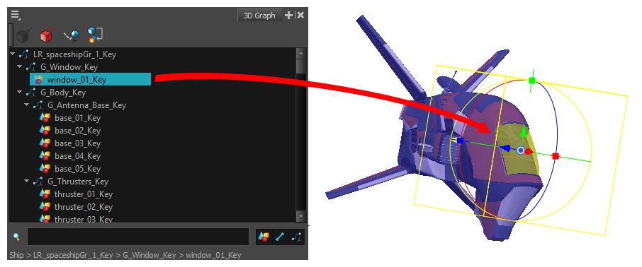
Using the 3D Graph view, you can see the list of subnodes available for the selected 3D model. Each subnode represents a part of the 3D model that can be transformed and animated independently, or even hidden. Like with peg hierarchies, subnodes that are children of other subnodes will be transformed along with their parents. If you select a subnode in the 3D Graph view, it will be highlighted in the Camera view, and the Transform tool will be set to manipulate that subnode rather than the whole 3D model.
You can also visually select a subnode in a 3D model by holding Ctrl (Windows/Linux) or ⌘ (macOS) and clicking on a part of the model in the Camera view. The corresponding subnode will be selected.
When a subnode is selected, you can transform it using the Transform ![]() tool the exact same way you would transform the whole 3D object—see About 3D Object Manipulation & Animation.
tool the exact same way you would transform the whole 3D object—see About 3D Object Manipulation & Animation.
If you make a transformation on a 3D model subnode directly, this transformation will be static. In order to animate a 3D model subnode, you must connect the 3D object's node to a Subnode Animation node, which will store the animation information for each of the model's subnodes that you animate. In both cases, the transformations and animations done on 3D model subnodes will appear in the final render, even if the model is rendered through Autodesk Maya.
It is also possible to rig an element in the scene to follow the animation of one of the subnodes of a 3D model.
Subnode Types
When a 3D model is selected, the model’s hierarchical structure of subnodes will appear in the 3D Graph view. The subnode list is comprised of Geometry, Bone and Transformation Subnodes. When you select a subnode in the 3D Graph view, it will be highlighted in the Camera view, and the Transform tool will provide set a 3D manipulator over the selection. You will have the capability to transform, activate or deactivate and apply modes to the selected subnode.
There are three types of subnodes that appear in the Subnode List. They are the following:
-
Geometry Subnodes.
-
Bone Subnodes.
-
Transformation Subnodes
Geometry Subnode
The Geometry Subnodes identify the polygonal shapes that construct the mesh of a 3D model. These shapes appear in the Render view and can be transformed with the Transformation tool.
Bone Subnode
The Bone Subnodes identify all the bones in the armature of the 3D model. Each bone will be listed based on its place in the hierarchy of the armature. By articulating the bone, the mesh of the 3D object can be transformed, affecting the geometry.
Transformation Subnode
The Transformation Subnodes apply an offset or transformation to an attached mesh and/or bone. When transformed, the subnode will apply its transformation to all connected children in the subnode graph. The Transformation Subnodes do not contain geometry or bone definitions and only supply a transformation
3D Graph View Layer Properties
The 3D Graph View Layer Properties dialog allows you to identify, sort, apply modes, and activate or deactivate all the subnodes in the subnode list.
In order to sort through and navigate the subnode hierarchy in the subnode list, you can use filters located in the bottom right corner of the 3D Graph View.
The Subnode List filter options are as follows:
-
Show Geometry Subnode
 .
. -
Show Bone Subnode
 .
. -
Show Transformation Subnode
 .
.
Using these filters, you can isolate a genre of subnodes in the subnode list.
With the filters applied, you can narrow your search by typing the subnode name into the Search bar.
For more information on the Search bar, see 3D Graph View.
Once identified and selected, subnodes can have modes applied to them using the 3D Graph Toolbar and/or 3D Graph View Menu. You can enable and disable selected subnodes, as well as apply modes to the 3D model.