The Surface Map is part of the Surface Shading set of nodes. It is a more advanced version of the Normal Map node and system. It provides a surface mapping that is used by the Surface Normal, Cast Shadow and Ambient Occlusion nodes, and it allows you to define height ranges in a rig or a scene that help define the surface being lit and shaded.
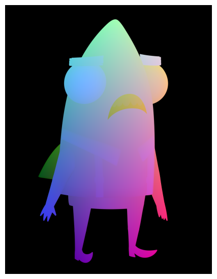
This mapping is different from the Normal Map, as it allows for the height ranges to interact relative to each other. A Surface Map is able to Cast Shadows from one elevation to another and interacts within the scene in field units.
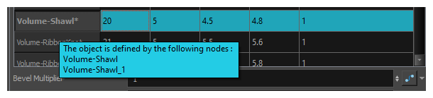
The Surface Map requires that Volume Objects be set up to appropriately define the surfaces. Once these Volume Objects have been created above the Surface Map, the map can be initialized.
Layer Properties
| Parameter | Description |
|---|---|
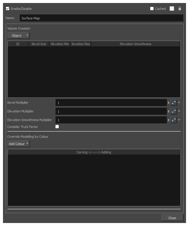
| Name | The name of the node as it appears in the Node View and the Timeline view. Each node must have a name that is unique to its containing group. |
| Volume Creation | |
| Object |
Allows you to add or remove Volume Object nodes that are connected to the Surface Map node to the Volume Creation list, so that you can specify their properties. The drop-down menu will list every Volume Object node connected to the Surface Map node so that you can add them individually, as well as the following commands:
|
| Volume Creation list |
Lists the different volume objects that are connected to the Surface Map node and which were added through the Object menu. In this list, you can define the basic volumetric shape and height range of each Volume Object node using the following fields:
|
| Elevation Smoothness Multiplier | A multiplier of the Elevation Smoothness value in the list. This affects every object listed. |
| Consider Truck Factor | Keeps the same ratio for the Light Shading system when the camera zooms in or out. |
| Override Modelling by Colour | |
| Add Colour |
Allows you to add or remove a Override Modelling by Colour list below. Zones that are painted with the colours added to the list will have more or less elevation. This allows you to use specific colours to carve from or add to the surface of the volume object, and add complexity to its surface. You can draw with one of the colours in the list on the Colour Art or Underlay Art layer so that the colour itself is hidden behind the artwork in the Line Art layer. The shape of the zone painted with this colour will still affect the surface. |
| Override Modelling by Colour list |
The list of colours that are used to override the surface of the volume object. Zones painted with the colours in this list will have a different elevation than the remainder of the volume object. Whether the elevation of the surface painted by the colour is lower or higher, and by how much, is determined by the value in the Carving <------> Adding field for that colour. If that value is higher than the Volume Object’s Elevation Baseline parameter, then the zones painted with that colour will be more elevated. If the value is lower than the Volume Object’s Baseline parameter, then the zones painted with that colour will be less elevated. |