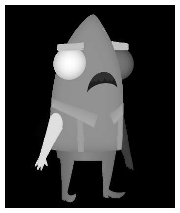
Different parts of a rig typically need to be placed at different elevations so that they generate cast shadows on each other. However, this causes hard seams to appear where different parts of a rig join together. For example, in the Height Map below, the character’s left arm is more elevated than their body, creating a hard seam around its shoulder which will make it “pop out” when a Cast Shadow effect is applied.
Displaying the blue channel of a Surface Map in the Camera view will show the relative heights of the surfaces in the Surface Map. This is helpful for setting up a character’s Volume Objects and blending the elevations of the surfaces. To generate this preview, see Previewing the Surface Map.
To fix this, a height map shape can be created to taper the height between the higher volume object and the lower volume object.
The first step is to create a single shape rig. The shape must be created to cover the part of the volume object that needs to be blended—see Creating Animatable Height Shapes for Surface Shading.
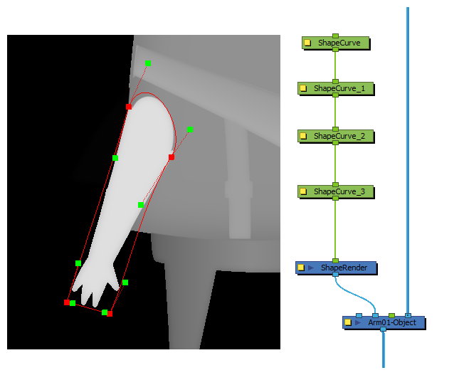
Then, the points that are closer to the joint must be moved down, so as to create a height map that will taper from the higher Volume Object’s height to the lower Volume Object’s height.
To move points backwards, select them and, while holding the Alt key, click and drag them downward. The points will shrink in size to indicate that they are further away from the camera.
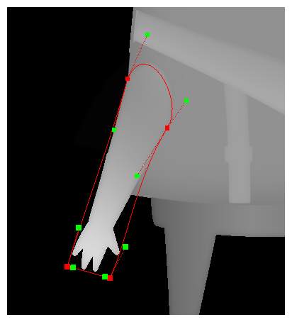
This causes the elevation of the arm to be sloped. The effect of this slope will be visible in the light, tone and cast shadow effects applied to the rig.
It is also possible to blend the joint by calculating the difference in elevation between the two Volume Objects, then applying this elevation difference to the control points near the joint. This allows you to blend the joints with much more precision, which should prevent even very subtle seams to appear near the joint.
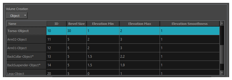
In this case, the elevation of the Arm01-Object needs to meet the elevation of the Torso-Object at the joint. Considering that:
- The Torso-Object has an elevation range from 1 to 2, while the Arm01-Object has an elevation range from 2 to 3.
- The Torso-Object’s Elevation Baseline parameter is set to 50%. Hence, with no height map applied, the elevation of the torso is of 1.5 field, since that is the middle point between its minimum elevation of 1 and its maximum elevation of 2.
-
The Arm01-Object’s Elevation Baseline parameter is also set to 50%. Hence, with no height map applied, the elevation of the arm is of 2.5 fields, since that is the middle point between its minimum elevation of 2 and its maximum elevation of 3.
This means that, when no height map is applied, the Arm01-Object is exactly 1 field (2.5 - 1.5) above the Torso-Object. Hence, in order for the shoulder and the torso to meet, the points around the shoulder need to be moved down by 1 field.
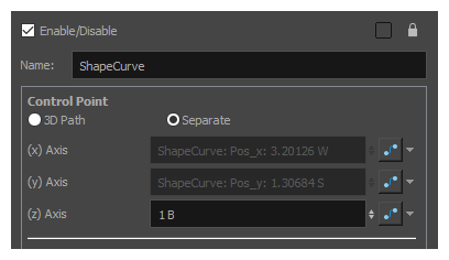
Since each point in a height map shape is a node, you can tweak the elevation of each point by opening the Layer Properties for its corresponding node, and entering the desired elevation for the point in its (z) Axis parameter.
In this case, the points near the joint need to be moved down 1 field. This can be accomplished by setting their position on the z-axis to 1 B.