
Adding 3D Objects to the Storyboard
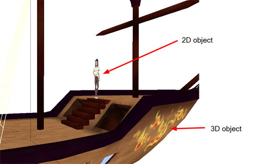
Once you have 3D elements, you can add them to your 2D scene in Storyboard Pro by dragging them into a panel, positioning and adjusting them so they fit in the scene, and animating them so that they interact smoothly with the 2D elements.
When you export a 3D element in FBX format, the export includes any textures you applied to it, so those textures will appear in the Shaded view. When you import the 3D element in Storyboard Pro and drag it into your scene. Also, if your 3D elements have pivot points, you can manipulate the objects using pivot points—see Modifying the Individual Nodes in the 3D Object.
This section includes the following topics:
| • | Importing 3D Objects to the Library |
| • | Inserting a 3D Object in a Panel |
| • | Modifying Imported 3D Objects |
| • | Animating 3D Objects |
Importing 3D Objects to the Library
When creating your animated project, you can import four types of 3D files by dragging them to the Timeline view. The supported 3D file formats are: *.osb, *.3ds, *.obj and *.fbx. When you import a 3D model, it is automatically added to the Library in the 3D Models folder according to its format. You can then reuse that 3D model easily within your project file.
When you import a 3D model into your library, each time you drag it into your scene, it continues to refer to the original model (it does not make a copy of the 3D model). The 3D Models library is also local to your project file, so you must import your 3D models in each project file.
To import a 3D object into the Library:
- In the Library view, right-click on the 3D Models library folder, and select Import Files.
The browser window opens.
- Locate your 3D file and click Open.
The selected 3D file appears in the Library view in a folder labeled according to its format (for example, OsbModels for *.osb files).
- Select the subfolder that represents the format of the model you imported. All the 3D models that match that format appear in the Library tab.
- Drag the 3D model to the Stage view.
The 3D model appears in its original size and is located at the zero NS/EW/FB position. The 3D model appears in all three view windows.
Replacing a 3D Model in the Library
Once you have imported a 3D model in the Library, you can easily replace it with a new one using the Replace 3D Model command. This will update all instances of the model used in the project.
To replace a 3D model:
- In the Library view, click the 3D Models folder to display its contents.
- From the 3D Models folder, select the model you want to replace.
- Right-click on the selected model and select Replace 3D Model.
A browser window opens.
- In the browser, locate the 3D model file you want to replace the selected model with, and click Open.
The Rename Node dialog box opens.
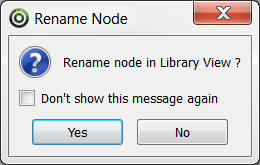
| ‣ | Click Yes to rename the replaced model using the new model name. |
| ‣ | Click No to preserve the replaced model name. |
| ‣ | Enable the Don't show this message again check box to prevent this dialog box from opening again, and use the same behavior as you choose now for future use of the Replace 3D Model command. |
The 3D model view is updated in the Library view and in your project at once.
Inserting a 3D Object in a Panel
Once you have a 3D object in your library, you can insert into a panel just like any other element: you drag it from the Library view to a panel and position it in the scene.
To insert a 3D object into a Panel:
- In the Library view, open the 3D Models folder and then open the format folder that contains your 3D object.
- Drag the 3D object into your panel, the Stage view, or Camera view window.
The object appears at its default size in the middle of the panel.
- To place or modify the 3D object, use the First Frame Transformation
 or the Last Frame Transformation
  buttons.
Once you placed your 3D object in a panel, you can do any of the following:
| • | Move, rotate, or transform your object—see Modifying Imported 3D Objects. |
| • | Animate the 3D Object—see Animating 3D Objects. |
| • | Display the various layers of the 3D object—see 3D Object Layer Display. |
Navigating 3D Space
Once your scene has been converted to 3D, you can rotate around your 2D and 3D objects in the Stage view using the keyboard shortcuts Once your scene has been converted to 3D, you can rotate around your 2D and 3D objects in the Stage view using the keyboard shortcuts [Ctrl]+[Shift] (Windows) or [Shift]+[⌘] (Mac OS X)[Ctrl]+[Shift] (Windows) or [Shift]+[⌘] (Mac OS X)
Modifying Imported 3D Objects
When you import a 3D object into a panel, you can place it in the 3D space much just as you would a 2D element by clicking directly on it and dragging it into place along the X, Y, and Z planes in the 3D space
When you select a 3D object in a panel, a 3D transformation bounding box appears around the object. This bounding box allows you to transform the object in any of the following ways:
| • | Rotating the object on a pivot point. |
| • | Changing the dimensions of the 3D object. |
| • | Modifying the individual nodes in the 3D object. |
Once you place your 3D object in your panel, you can create some basic animation with it using the First and Last Frame feature. Being able to animate your 3D object allows you to create interaction between 2D and 3D elements.
This section includes the following topics:
| • | Rotating a 3D Object Along a Pivot Point |
| • | Changing the Dimensions of the 3D Object |
| • | Modifying the Individual Nodes in the 3D Object |
| • | Reverting a 3D Object to its Original State |
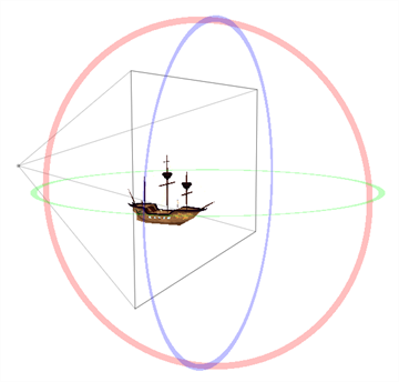
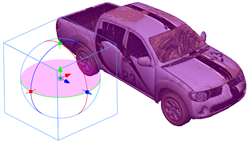
Rotating a 3D Object Along a Pivot Point
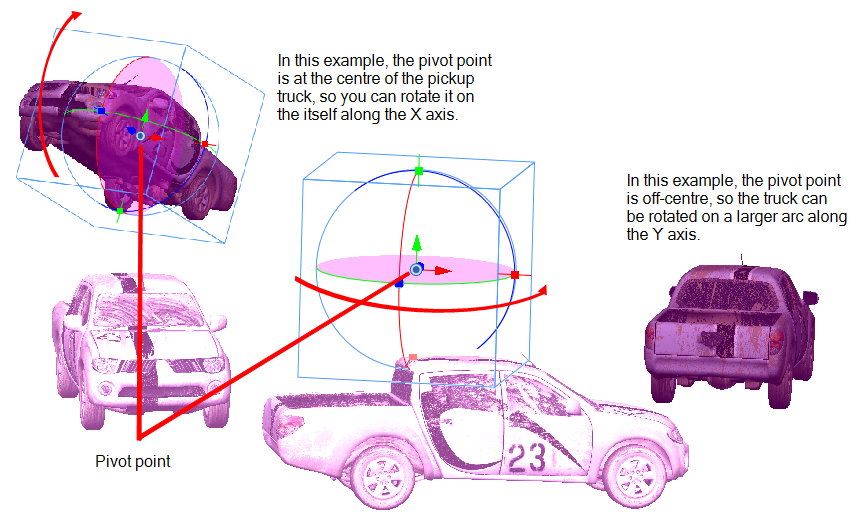
The pivot point defines the size of the arc upon which you will apply the rotation to the 3D object. When the pivot point is in the centre of the object, the object rotates upon itself. But when you place the pivot point on the outside of the object, the object will rotate a larger axis with the pivot point at the centre.
|
|
|
|
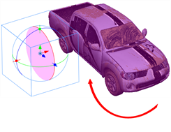
Rotation along the X-axis |
Rotation along the Y-axis |
|
|
|
|
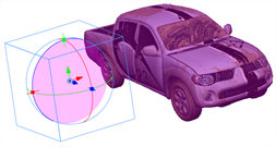
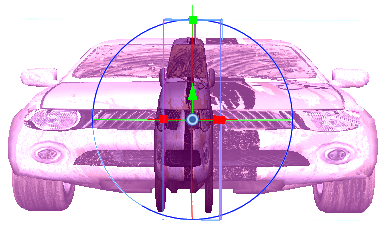
Rotation along the Z-axis |
Resizing the 3D object
|
In the above examples, the pivot point was moved to the side of the object for illustrative purposes. By default, the pivot is positioned below the 3D object at its centre. Depending on the pivot point’s position, the object’s rotation arc will change.
To rotate a 3D element along a pivot point:
- Click the First Frame Transformation button and select an element from your scene in the Stage view.
A bounding box appears around the element and the layer appears highlighted in purple in the Top and Side views.
- Drag the pivot point
 to the location at which you want to base the rotation.
- Using the X-axis, Y-axis, and Z-axis guiding lines, change the Yaw, Pitch, and Roll of the object.
As you place the cursor on the guide lines, it will change to display with axis is being changed. Use the view windows to see how the object looks from the Camera, Top, and Side views.
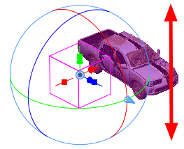
Changing the Dimensions of the 3D Object
When you import a 3D object, it appears in its initial size and dimensions. Using the control points on the bounding box, you can change these dimensions of the object:
| • | Width (X-axis) |
| • | Height (Y-axis) |
| • | Length (Z-axis) |
| • | Overall size (X, Y, Z axis in proportion) |
|
|
|
|
Resizing along the X-axis |
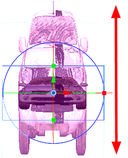
Resizing along the Y-axis
|
|
|
|
|
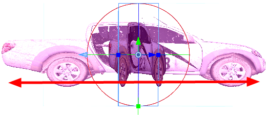
Resizing along the Z-axis |
Resizing the whole 3D object |
To rotate a 3D element along a pivot point:
- Click the First Frame Transformation button and select one of the elements in your scene from the Stage view.
A bounding box appears around the element and the layer appears highlighted in purple in the Top and Side views.
- Drag one of the X-axis, Y-axis, and Z-axis control points to change any of the following dimensions:
| ‣ | Width (X-axis) |
| ‣ | Height (Y-axis) |
| ‣ | Length (Z-axis) |
| ‣ | Size (X, Y, Z axes in proportion) |
Use the views to see how the object looks from the Camera, Top, and Side views.
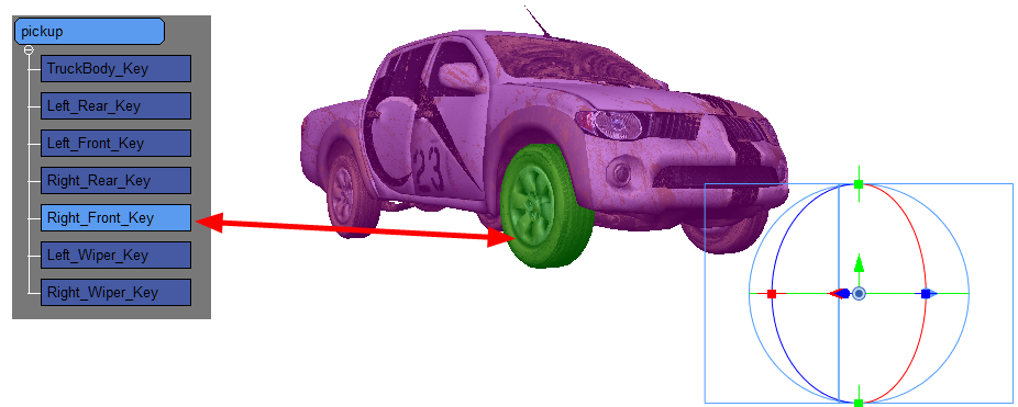
Modifying the Individual Nodes in the 3D Object
3D objects often consist of multiple nodes or meshes that are combined to form the entire object. If you look at the pickup truck examples in this chapter, you can see that it consists of:
| • | A body |
| • | Four wheels |
| • | Two wipers |
Just as you can transform the object as a whole, you can also apply transformations to the individual nodes of the 3D object.
To select individual nodes in the 3D object:
- Click the First Frame Transformation button and select one of the elements in your scene from the Stage view.
A bounding box appears around the element and the layer appears highlighted in purple in the Top and Side views.
- To select a node in the 3D object, select Window > 3D Nodes.
The 3D Nodes window opens. You can change how the hierarchy appears in this window using the following commands:
| ‣ | Zoom In/Out: Increases (zoom in) or decreases (zoom out) the magnification. You can also press [1] to Zoom Out or press [2] to Zoom In. |
| ‣ | Reset Zoom: Restores the magnification to its default setting. |
| ‣ | Reset Pan: Resets the 3D node tree to its default position. |
| ‣ | Reset view: Restores the 3D node tree to its default position and magnification. |
You can reposition the 3D node tree in the window by pressing the [Space bar] and dragging the cursor inside the 3D Node window.
- Select one of the nodes of the 3D object.
The selected node appears highlighted in green and a bounding box appears.
- You can also select the nodes using [Ctrl]+click (Windows) or [⌘]+click (Mac OS X). To select all the nodes, right-click the 3D Nodes window and select Select All.
By default, the basic node structure appears in the 3D Nodes window.
- Using the bounding box, you can make the following changes to the node:
| ‣ | Its position in the 3D space |
| ‣ | Its Yaw, Pitch, Roll rotation (use the pivot point to change the arc size) |
| ‣ | Its dimensions along the X, Y, and Z-axis |
This section includes the following topics:
| • | Resetting Changes to 3D Nodes |
| • | Configuring the 3D Nodes Feature |
Resetting Changes to 3D Nodes
When you import a 3D element that contains 3D nodes, all these nodes are in their default position and size/proportion. You can make changes to these nodes, but if you want to reset a node to its default position (undoing all the changes you made), you can restore each node to its default settings.
To restore a node’s default settings:
- Select the node you wish to restore by [Ctrl]+clicking the node in a view window or by selecting it from the hierarchical position in the 3D Nodes window.
If you use the 3D Nodes window, you can select multiple nodes by [Ctrl]+clicking each one.
- Select Layer > Reset Selected 3D Nodes. The selected nodes return to their default settings.
Configuring the 3D Nodes Feature
You can use the 3D Nodes UI tab in the Preferences to change how the hierarchy is displayed in the 3D Nodes window.
To configure the 3D Nodes interface:
- Select Edit > Preferences and select the 3D Nodes UI tab.
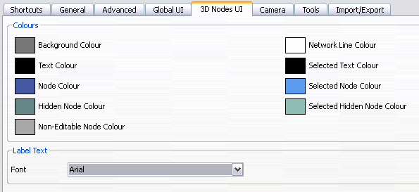
- In the Colours section, select the colour to display for each item in the 3D Nodes window. These colour selections only apply to the features in the 3D Nodes window; they do not apply to the 3D element in your scene.
- In the Label Text section, determine how the text is displayed in the 3D Nodes window from the Font menu.
Reverting a 3D Object to its Original State
If you make changes to the 3D object, such as its dimensions, position, or rotation, and you want to revert back to the object’s original settings, you do not need to delete the object and start over. You have couple of options:
| • | You can use the Undo command to undo any of the changes you made to the object or in the panel since the project was last saved. |
| • | You can use the Reset Transform command to revert to the object’s original settings (position and dimensions). |
The Reset Transform command will only affect the selected element, reverting it back to its default dimensions, position, and rotation for all the frames in the panel (First Frame and Last Frame).
To revert the 3D object to its original state:
- Select the 3D object in your panel.
- Select Layer > Reset Transform.
Animating 3D Objects
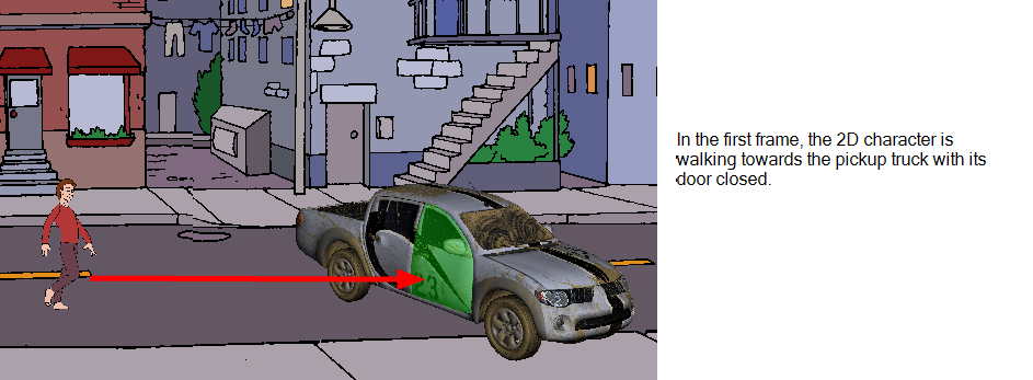
Now that you understand all the different changes you can make to a 3D object in your panel, you can create an animation with it using the first and last frame of the panel. You can modify the object in the first frame of the panel, modify the object in the last frame of the panel, and Storyboard Pro will transform the object from its first state to the last state at a speed defined by the duration of the panel.
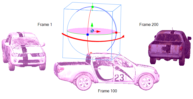
In the above example, the pickup truck starts on the left at frame 1 and ends on the right at frame 200. Storyboard Pro interpolates the various positions and rotations of the pickup truck as it moves from its initial state to its final state.
To animate a 3D element in the 3D space:
- Click the First Frame Transformation button, select an element in the scene, and place it in its initial state. You can also make a multiple selection to move multiple 3D layers at once.
- Make any of the following changes to the object:
| ‣ | Position in 3D space |
| ‣ | Yaw, pitch, roll rotation (use the pivot point to change the arc size) |
| ‣ | Dimensions along the X, Y, and Z-axis |
You can also make changes to the individual nodes that make up the object.
- Click the Last Frame Transformation button, select the same element, and place it in its final state.
- Repeat step 2.
- Click the Play
 button to see the animation of the element as it moves from the first frame position to the final frame position.