Effect Stack View
The Effect Stack view is used to apply effects to drawing layers and edit sound clips by layering effects onto the clip. The parameters of these effects can be adjusted to fine tune the desired result.
- Do one of the following:
- In the Top menu, Select Windows > Effect Stack.
- In any view, click the Add View
 button and select Effect Stack.
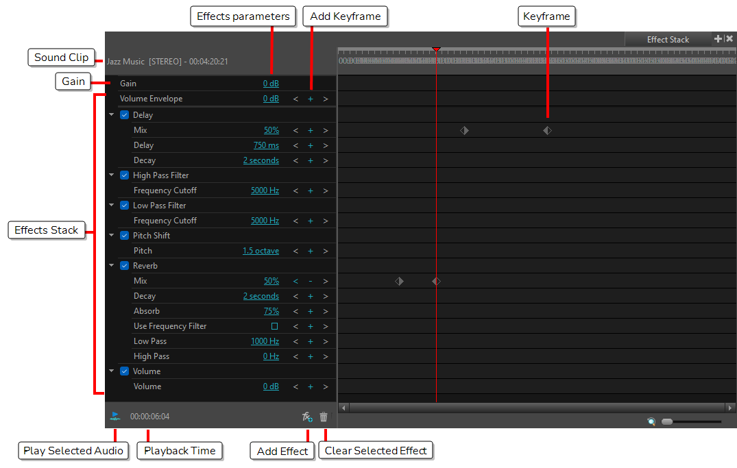
| Sound Clip | Where the selected sound clip name is displayed. This includes the file name, file format and whether the file is mono or stereo (indicated in square brackets). The sound clip name is followed by the current time location of the playhead in the Timeline view. |
| Effects Stack | Where effects are displayed. These effects can be disabled, enabled, have their parameter values modified or be deleted from the list. |
| Effects Parameters | The values for each effect |
| Add Keyframe |
When clicked, a keyframe will be applied for the effects. See Effect Stack. To navigate one keyframe to the right, select the Right arrow. To navigate one keyframe to the left, select the Left arrow. |
| Play Selected Audio |
Click the Play Selected Audio button to playback the selected sound clip directly in the Effect Stack view. TIP The Play button will change to a Stop button while the audio is playing. Click the Stop button to stop the audio playback.
Clicking Play will always play the audio from the beginning. |
| Playback Time | Indicates the playback time location. |
| Add Effect | Click on the Add Effect button to display a list of sound effects that can be applied to the selected sound clip. Selecting an item from the list will add this effect to the bottom of the Effect Stack. |
| Clear Selected Effect | After selecting an effect from the Effect Stack, click on this button to delete the effect from the stack. |
| Keyframe | The keyframe applied to the effect. |
Layer Effects
| Effect | Description | ||||||||||
|---|---|---|---|---|---|---|---|---|---|---|---|
| Gaussian Blur |
Softens the image reducing the amount of noise and detail. Gaussian Blur parameters: Directional: Blurs according to the length, width, and angle you specify. For example, if a character is walking east, the blur may fall to the west. Horizontal Blurriness: Length of the Blur Vertical Blurriness: Thickness of the blur. Angle: The direction in which the blur is applied: sideways, up, down, 90 degrees, 45 degrees, and so on. Bidirectional: Blurs in both horizontal and vertical directions. Repeat Edge Pixels: Makes the blur algorithm operate as if the pixel values beyond the edge of the layer are the same as the values of the edge pixels. This keeps edges sharp, preventing them from darkening and becoming more transparent. |
||||||||||
| Directional Blur |
Blurs according to the length, width, and angle you specify. Directional Blur parameters:
|
||||||||||
| Unsharp Mask |
Increases the contrast between the surrounding pixels resulting in a sharper image. Unsharp Mask Properties:
|
||||||||||
| Contrast |
Increase or decrease the level of contrast in an image. Contrast parameters:
|
||||||||||
| Brightness Contrast |
Modify the brilliance or dullness of an image. Brightness Contrast parameters:
|
||||||||||
| Greyscale |
Convert a colour image to greyscale. Greyscale parameter: Percent: The percentage of greyscale to apply to the input image. Lowering this parameter will only partially desaturate the image's colours. |
||||||||||
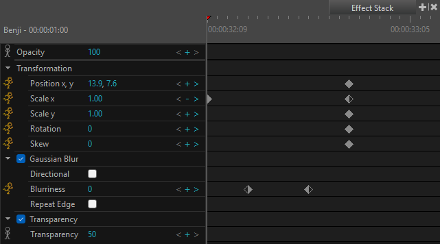
| Transparency |
Reduce the opacity of your image by making an image partially transparent. Transparency parameter: Transparency: Lets you set the opacity of an element. Values range from 0 to 100. A value of 100 will make the element 100% transparent and a value of 0 will render the element completely opaque. |
||||||||||
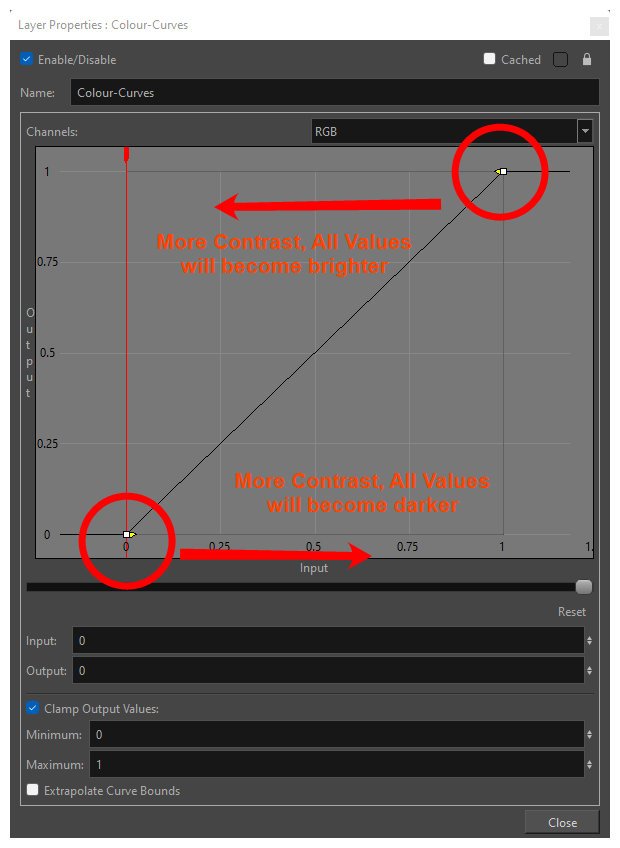
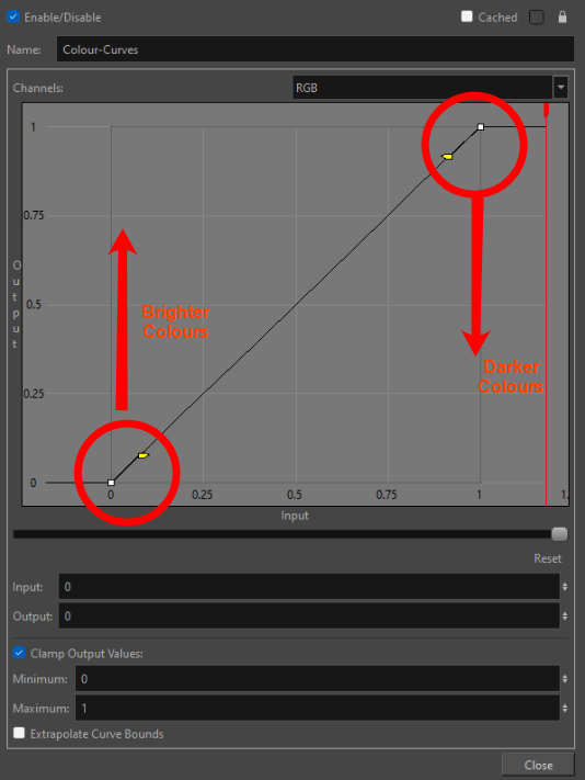
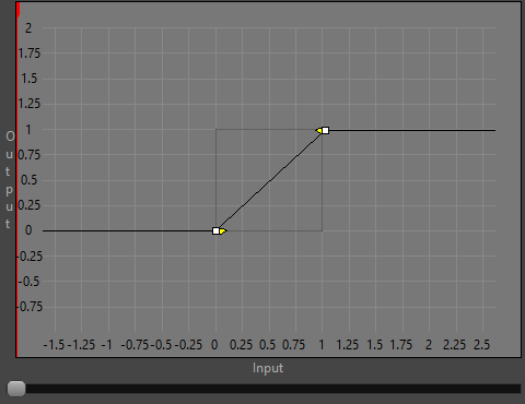
| Colour Curves |
Modify the brightness and contrast of an image. Depending on if you modify the input, the output values or a mix of both, you can darken the shadow of a picture, brighten the highlights.
|
||||||||||
| Colour Levels |
Adjust the levels in an element in order to find a balance between the black and white values in an image.
|
||||||||||
| Blending Modes |
Choose the blending effect mode you wish to apply to your layer.
|
Sound Effects
| Effect | Description |
|---|---|
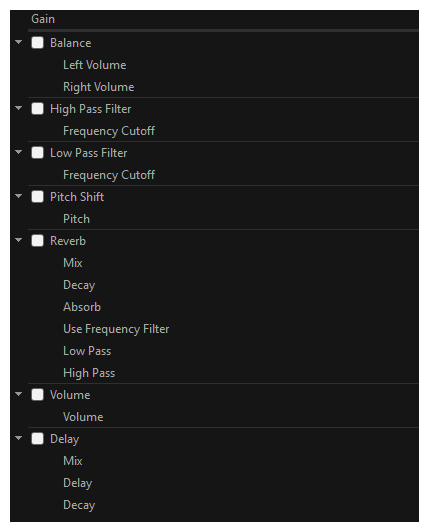
| Gain | A default effect in the Effect Stack with a decibel (dB) value of 0. Controls how loud the selected sound clip is before it goes through any processing (other effects are added). The gain value (loudness) can affect the tone of the sound clip as it goes through processing. |
| Balance | Applies volume independently to the left or right channel. Only works on clips with stereo sound. Mono audio clips will duplicate the audio in each channel and then apply the volume. |
| Left Volume | Sets the distribution of volume being applied to the left channel in decibels (dB). |
| Right Volume | Sets the distribution of volume being applied to the right channel in decibels (dB). |
| High Pass Filter | Passes frequencies higher than the Frequency Cutoff and mutes frequencies lower than the Frequency Cutoff. Will cut out all the bass of the audio clip and sounds tinnier. |
| Frequency Cutoff | Set point for passing frequencies below this value, while muting those above this point. Minimum = 0 hz (no frequencies pass), maximum = 22050 Hz (all frequencies pass). |
| Low Pass Filter | Passes frequencies lower than the Frequency Cutoff and mutes frequencies higher than the Frequency Cutoff. |
| Frequency Cutoff | Set point for passing frequencies above this value, while muting those below this point. Minimum = 0 hz (all frequencies pass), maximum = 22050 Hz (no frequencies pass) |
| Pitch Shift | Allows the pitch to be raised or lowered by a defined octave value. |
| Pitch |
Sets the value in octaves by which to shift the pitch, where 0 octaves will result in the original audio. A positive value will increase the pitch, while a negative value will decrease the pitch. Octaves are on a logarithmic scale. This means that shifting the pitch up by one octave (+1) doubles the sound's frequency, while shifting the pitch down by one octave (-1) puts the sound at half its original frequency. |
| Reverb | Creates a reverberation effect that mimics the way sound bounces within an enclosed space. |
| Mix |
The wet and dry balance percentage of the echo effect, as it is mixed with the original source audio. A value of 0% will be dry, playing only the source audio. A value of 50% will blend the source audio and effect 50/50. A value of 100% will be wet, playing only the effect. |
| Decay | The time decay in seconds (s) for the length that an audio source reverberates within a space. A higher decay time sustains the reverberation for longer and produces more internal reverbs. A lower decay time results in a sharper reverberation. |
| Absorb |
The amount as a percentage (%) that the reverberating audio is absorbed on each sample pass A lower absorption percentage allows the audio to endure for longer. A high absorption value muffles the reverberation faster. A 100% absorb value will result in no reverberation. |
| Use Frequency Filter | Determines whether the Reverb effect stifles frequencies outside a certain range. When this option is checked, the High Pass and Low Pass filters affect the sound clip's audio frequencies by their selected values. Without this option checked, frequencies will reverberate consistently. |
| Low Pass | When the Use Frequency Filter option is enabled, this value defines what frequencies can pass on each reverberation. Frequencies below this value will be audible, but frequencies above it will be muted. This parameter can be adjusted to create hollower sounding rooms and larger spaces. |
| High Pass | When the Use Frequency Filter option is enabled, this value defines what frequencies can pass on each reverberation. Frequencies above this value will be audible, but frequencies below it will be muted. This parameter can be adjusted to create bouncier sounding rooms with harder walls. |
| Volume | Controls how loud the sound clip is after it has been processed. |
| Volume | Increase the decibel (dB) value to a number greater than 0 to increase the loudness of the selected sound clip or to a value less than 0 to decrease loudness, where 0 is the starting value. Unlike gain, the volume's loudness will not affect the tone of the sound. The Volume range is -96 dB to +6 dB. |
| Delay | |
| Mix | The percentage volume of the echo effect, as it is mixed with the original source audio. A value of 100% will only play the effect, whereas a value of 0% will only play the source audio. |
| Delay | Defines the delay between the original source audio and the initial echo reverberation, as well as between each subsequent reverberation. This value is in milliseconds (ms). |
| Decay |
Defines the point at which the echoing source can no longer be heard. This value is in seconds (s). If there is more than one echo, each subsequent echo will get quieter and quieter over the length of the decay. Given a delay of 500 ms and a decay of 2 seconds (2000 ms), the listener will hear a total of 4 individual echos (2000 ms decay / 500 ms delay). |