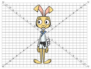
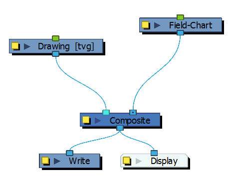
The Field Chart node displays a traditional animation field chart, which allows you to position elements in the Camera view. The Field Chart node doesn't export. If you want to export a field chart, use the Grid node—see Grid Node.
Field Chart Properties
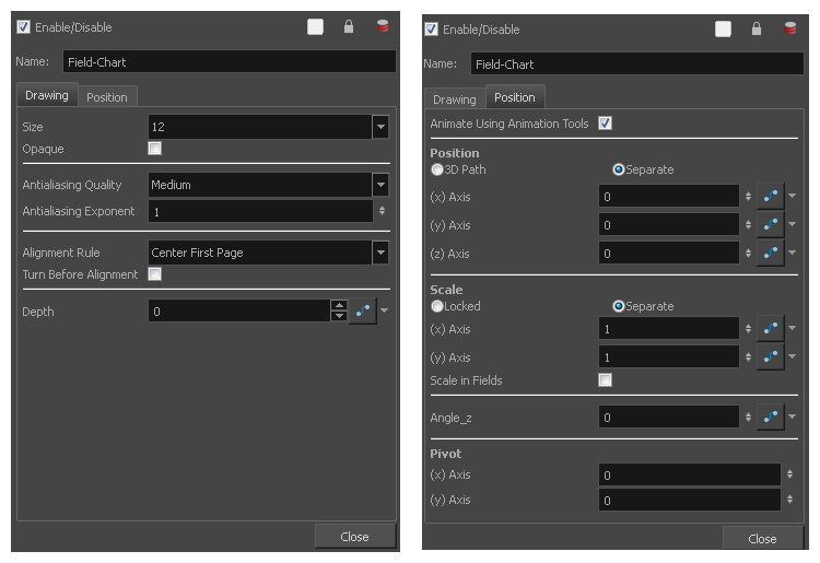
| Parameter | Description |
| Name | Allows you to change the name given to the node. |
| Drawing | |
| Size |
Adjusts the number of units in the grid (field chart). The grid size will always be a 4:3 ratio, as per traditional animation standards. The gird is available in 12 or 16 fields. |
| Opaque |
Inserts a white background behind the grid and covers everything else behind it. By default, you can see through the grid. |
| Antialiasing |
Antialiasing Quality: The smoothness (antialiasing) setting used to make the crisp vector contours appear smooth.
TIP It is recommended to leave this setting to High unless you are working on a pencil test, or another type of scene where rendering speed is more important than rendering quality.
TIP If the production requires exporting line art without antialiasing to colour them in a third-party software, it is recommended to use the None - No Transparency setting. This setting automatically fills one-pixel gaps created by crisp lines intersecting each other, which would otherwise need to be filled manually in the third-party software.
Antialiasing Exponent: Determines how much the artwork is scaled up to apply antialiasing onto it. A higher value will results in sharper edges, and a lower value will result in softer edges. Typical values range between 0 and 3. Higher values may be attempted but may result in overly crisp outlines. Negative values will cause the outlines to appear blurry. |
| Alignment Rule |
The alignment rule selections are intended to deal with drawings that were created on paper of a different size or orientation from the default alignment rule (set up in the Scene Settings dialog box) or imported bitmap images. The drawings are then scaled to match the Harmony alignment rectangle. Note that alignment rules are not based on the camera frame, but on the scene frame. Refer to the Fundamentals Guide to learn more about scene alignment and scene settings.
|
| Turn Before Alignment |
Turn Before Alignment: Rotates the drawings in the selected element 90 degrees to the left before scaling and aligning them according to the alignment rule, and before performing any offset, rotation or scaling for the element or peg. This and the Alignment Rule are intended for drawings that were created on paper of a different size or orientation than the other paper in the scene, and requires alignment so they are treated accurately. |
| Depth |
Overrides the order of cables in the node system to determine the forward/backward order in which this element is rendered. The Z position value overrides the depth value. |
| Position | |
| Animate Using Animation Tools |
By default, the grid can be animated using the same parameters as a peg, but you can disable this feature so the field chart remains in place. You can connect it to a peg to animate it or move it. When this option is deselected, you cannot move the layer in the Camera view using the Transform and Advanced tools. This prevents you from accidentally displacing or modifying a layer. |
| Position |
3D Path: Use a 3D path to position the element. A 3D path uses a single function to define the position on the X, Y and Z axes. This function is made of control points linked by a curvilinear path, making the movement follow a natural curve. The pace and ease of the movement is determined by a single velocity function. Separate: Positions the element using separate functions for the X, Y and Z axes. This allows to control the direction and pace of the movement across all three axes separately. Unless ease is applied to the axes, the trajectory of the element will follow straight lines going between each keyframe. Path: If the 3D Path option is selected, this field allows you to create or select the 3D Path function used to position the element. Path (x) Axis: The position of the element on the East-West axis, in fields. Path (y) Axis: The position of the element on the South-North axis, in fields. Path (z) Axis: The position of the element in the Back-Front axis, in fields. Velocity: If the 3D Path option is selected, this function is used to control the pace at which the element moves towards each control point in the 3D Path function, on all three axes simultaneously. |
| Scale |
Locked: Uses a single scale parameter to scale the element, preserving its proportions. Separate: Uses a separate parameter to scale the element on the X and Y axis (x) Axis: The horizontal scale factor. The default value is 1. (y) Axis: The vertical scale factor. The default value is 1. (z) Axis: The depth scale factor for 3D-enabled elements. The default value is 1. Scale in Fields: With this option enabled, the scale factor is based on the amount of fields in the scene. For example, to shrink one of the dimensions of an element to half its original size, the scale factor would normally bet set to 0.5. If this option is enabled and the amount of fields in the scene is 12, then the scale factor to shrink the element by half would be 6. |
| Angle Z |
Lets you type in a degree value for the rotation angle. Note that you can enter values greater than 360 and -360 degrees. If you enter 720, the object will rotate twice. |
| Pivot |
(x) Axis: The horizontal position of the pivot point of the element relative to the pivot point of the drawing, in fields. (y) Axis: The vertical position of the pivot point of the element relative to the pivot point of the drawing, in fields. |