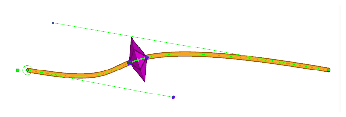
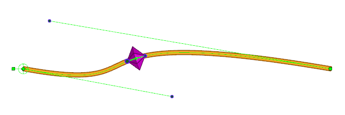
The Point Kinematic Output node is a more advanced version of the Kinematic Output node. It tracks a point that can be placed anywhere on a deformation curve, and moves the drawing that is attached to it so that it remains stuck on that deformation curve, without deforming the drawing itself.
Additionally, it can:
- Make the angle of the drawing match the angle of the curve at the point where it’s rigged.
- Scale the drawing to make it match the size of the area of the curve the drawing is rigged to.
- Rig the drawing to three points in the deformed drawing, which can be useful for rigging a drawing somewhere inside the deformed drawing without necessarily making it stick to the curve.
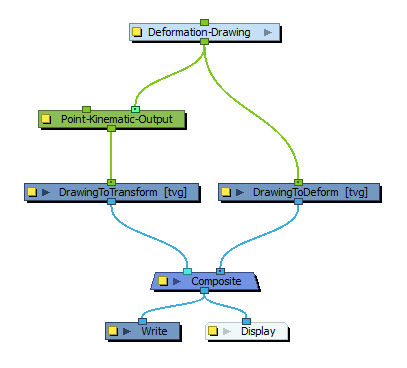
Connections
The Point Kinematic Output has a deformation input port (rightmost) and an offset transformation port (leftmost). It takes the deformation sent to its rightmost port and outputs a transformation, without any deformation, through its only output port. If no deformation is attached to the node, the node will have no effect in the rig.
When no node is connected to the offset transformation port, the positions that the node tracks within the deformation will be based on the tracking positions in the node’s properties. This is the most simple usage scenario.
When a transformation module, such as a peg, is attached to the leftmost port, the tracking points will be offset based on the attached transformation to the port.
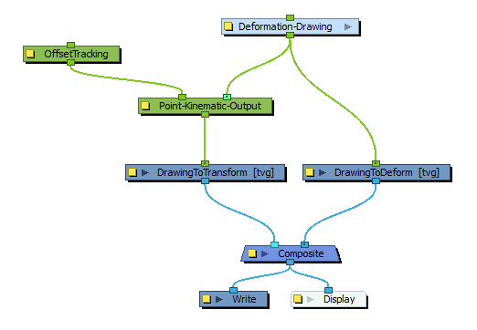
The leftmost port can then be used to offset the tracking points in a rig based on the transformation of other attached nodes in that rig.
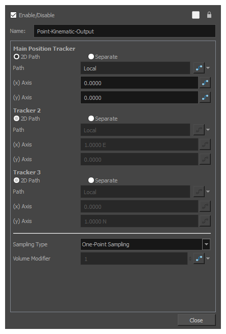
Layer Properties
| Parameter | Description |
|---|---|
| Main Position Tracker |
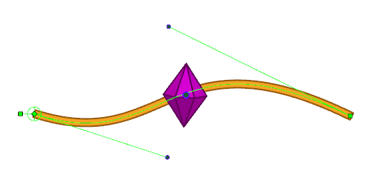
The position of the central point used in all sampling types. In One-Point Sampling, this point is used to track the translation in the deformation. In the other sampling-types, it is used to help define the transformation with the other relative points. TIP
You can display this point in the Camera view and manipulate it with the Transform tool by displaying the node’s controls. To do this, select the node in the Node View and do one of the following:
If you set the Sampling Type to use two or three points, you can also see and manipulate the other points in the Camera view. |
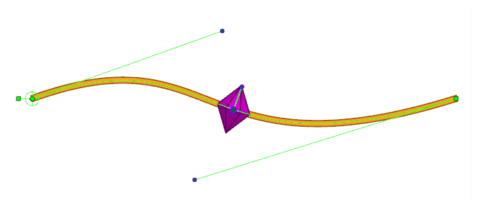
| Tracker 2 |
The second sampling point is used in Two-Point Sampling, Two-Point Sampling with Scaling and Three-Point Sampling. This point is used to help define the orientation in Two-Point Sampling, It helps to define the orientation and scale in Two-Point with Scale sampling, and helps to define the orientation, scale and skew in Three-Point Sampling. |
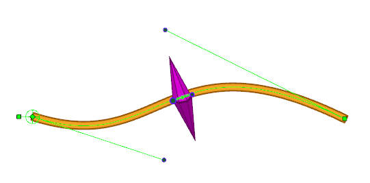
| Tracker 3 | The third sampling point is used in Three-Point Sampling. It helps to define the orientation, scale and skew of the resulting transformation. |
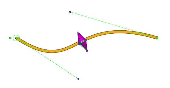
| Sampling Type |
The Sampling Type defines the number of points that track the deformation and which are then used to transform the attached drawing, as well as how those points are used to transform the drawing.
|
| Volume Modifier |
The Volume Modifier is applied only when using the 2-Point with Scale sampling type. With this sampling type, the drawing is scaled on the axis between the Main Position Tracker point and the Tracker 2 point based on the distance between those two points. The distance between those points varies relative to the length of the deformation curve as it is modified. In other words, the drawing is stretched when the curve is made longer, and it is squashed when the curve is made shorter. To preserve the drawing’s volume, a scale is also applied on the perpendicular axis. This scale is automatically calculated so that the drawing always keeps the same volume. So as to give you control on this, the scaling applied on the perpendicular axis is proportional to the Volume Modifier parameter. A Volume Modifier set to 1.0 will result in a squash-and-stretch that preserves the volume of the transformation. As the axis defined by the two tracking points is squashed, the perpendicular axis is stretched to preserve the volume. If the axis is stretched, then the perpendicular axis is squashed instead.
A Volume Modifier set to 0.0 will result in a transformation that does not attempt to preserve the volume of the transformation. As the axis defined by the two tracking points is squashed, no scale is applied to the perpendicular axis.
You can set the Volume Modifier parameter to any value between 0 and 1 so as to mitigate the effect of the perpendicular scaling and prevent it from deforming the drawing too much, but any value lower than 1 means the volume of the drawing will not be fully preserved. |