The Drawing layer is at the core of a scene's structure. A drawing layer is linked to an element, which contains a series of drawing, and its Xsheet column, which indicates when and for how long each drawing is exposed. The layer is what connects the element and its exposure to the rendered image. It indicates the position of the drawings relative to other elements and to the stage, as well as the drawing's connections with pegs, groups and effects, if any.
Although drawing layers can be transformed and animated on their own, it is typical to connect them under a parent peg. This allows you to keep the position and animation information of the element in the peg, making it easier to manipulate the exposure and the transformations separately. This is especially useful in digital cut-out animation where manipulating and transforming layers is often the main method of simulating movement, and changing drawings is the secondary method.

You can also connect a drawing layer as a child of another drawing layer. Just like with pegs, any transformation done to the parent layer, whether on itself or through one of its parents, will also be applied to the child layer.

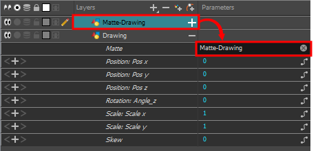
Optionally, you can connect a matte drawing to a drawing layer. When a drawing layer has a matte drawing, only the parts of the drawings that intersect with the opaque areas of the matte drawing will be rendered. This allows you to accomplish the same effect as connecting the drawing layer to a cutter effect.

Layer Properties
The drawing layer's properties are organized in the following tabs:
Transformation Tab
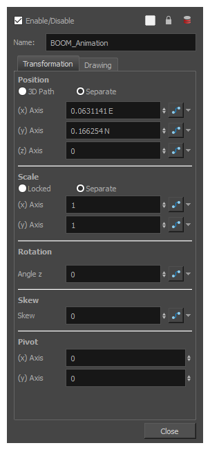
The Transformation tab contains parameters for adjusting the position, scale, rotation, skew and pivots of an element.

| Parameter |
Description |
| Position |
3D Path: Use a 3D path to position the element. A 3D path uses a single function to define the position on the X, Y and Z axes. This function is made of control points linked by a curvilinear path, making the movement follow a natural curve. The pace and ease of the movement is determined by a single velocity function. Separate: Positions the element using separate functions for the X, Y and Z axes. This allows to control the direction and pace of the movement across all three axes separately. Unless ease is applied to the axes, the trajectory of the element will follow straight lines going between each keyframe. |
|
Path: If the 3D Path option is selected, this field allows you to create or select the 3D Path function used to position the element. Path (x) Axis: The position of the element on the East-West axis, in fields. Path (y) Axis: The position of the element on the South-North axis, in fields. Path (z) Axis: The position of the element in the Back-Front axis, in fields. Velocity: If the 3D Path option is selected, this function is used to control the pace at which the element moves towards each control point in the 3D Path function, on all three axes simultaneously. |
|
| Scale |
Locked: Uses a single scale parameter to scale the element, preserving its proportions. Separate: Uses a separate parameter to scale the element on the X and Y axis, allowing to stretch or squash the element. |
|
(x) Axis: The horizontal scale factor. The default value is 1. (y) Axis: The vertical scale factor. The default value is 1. |
|
| Rotation |
Angle z: The angle at which the element is rotated, based on the 360 degrees scale. Values below 0 or above 360 degrees will cause the rotation to cycle. |
| Skew |
Skew: The angle at which the element is skewed. This value can range from -90 to 90 degrees. |
| Pivot |
(x) Axis: The horizontal position of the pivot point of the element relative to the pivot point of the drawing, in fields. (y) Axis: The vertical position of the pivot point of the element relative to the pivot point of the drawing, in fields. NOTE These parameters can be changed visually by clicking and dragging the pivot point when using on of the tools in the Advanced Animation toolbar.
|
Drawing Tab

| Parameter |
Description |
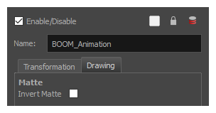
| Matte | Invert Matte:
|
| Colour Space |
Colour Space: The colour space in which the element’s colours should be interpreted. If the element’s colour space is different from the project colour space, then the element’s colours will be converted from the element’s colour space to the project’s colour space as they are processed, before being composited together with the scene’s special effects.
NOTE
In the |