As explained in Defining and Animating Elevation, it is possible to add shape definition to a Volume Object by connecting a drawing to it. But it is also possible to create basic animatable shapes and use them to add shape definition to a Volume Object. This allows you to animate parts of the surfaces in your surface shading system.
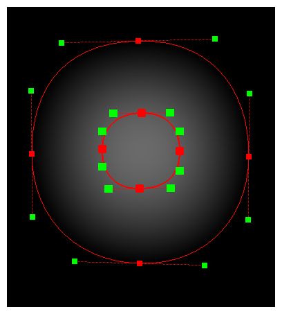
This is done by creating a system of Shape Line, Shape Curve and Shape Render nodes, and connecting it to the Height Map port of your Volume Object.
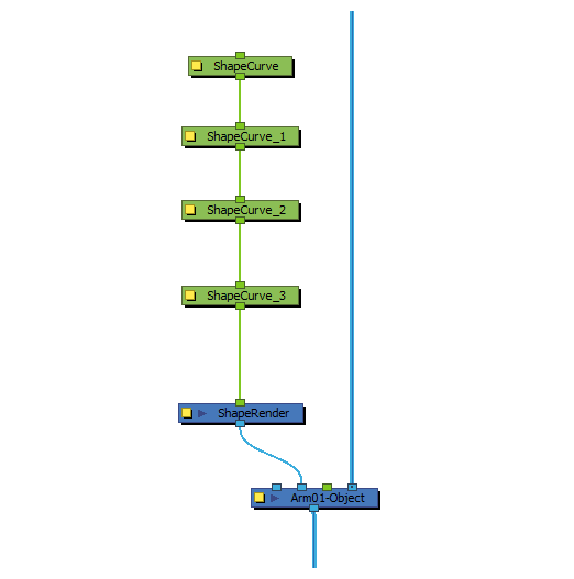
While the Shape Line and Shape Curve nodes define the points of the shape, the Shape Render node combines those points to generate shapes, and fill those shape with a height map, which can then be used by the Volume Object node, instead of a drawing or bitmap image.
- In the Node Library view, in the Shading category, select a Shape Render node and drag it to the Node view. This node acts as a composite for all attached Shaped nodes.
-
In the Node Library view, in the Output category, select a Display node and drag it to the Node view. Then, connect the output port of the Shape Render node to the input port of that Display node.
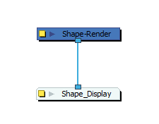 NOTE This Display node will be used to preview your shape as you build it.
 - In the drop-down in the Display toolbar at the top of the user interface, select the Display node you just created to preview it in the Camera view.
-
In the Node Library view, in the Shading category. Then, do one of the following:
- If you want to create a polygonal shape, select a Shape Line node and drag it to the Node View.
- If you want to create a curved shape, select a Shape Curve node and drag it to the Node View.
A single Shape Line or Shape Curve node defines a single point in the shape of the region. Hence, you must repeat this process until you have as many Shape Line or Shape Curve nodes as necessary to define each point in the shape of the region you want to create.
For example, if you want to create a rectangle, you would need four Shape Line nodes, one for each of the four points defining a rectangle. If you want to create an ellipsis, you would need four Shape Curve nodes instead.
-
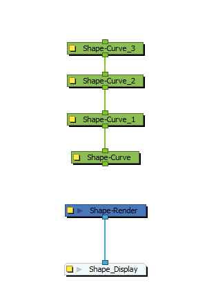
Position the Shape Line or Shape Curve nodes vertically, and connect them in a chain.
-
Connect the output port of the lowest Shape Line or Shape Curve node to the Shape Render node.
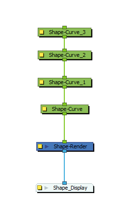 NOTE Like a Composite node, the Shape Render node will create as many input ports as you connect nodes to it. This is because you can combine several shapes by connecting several chains of Shape Curve or Shape Line nodes to the Shape Render node.TIP Shape Line and Shape Curve nodes can be used together, to create shapes that are made of curves and straight lines.
 -
Select the Shape Render node and display its controls in the Camera view by doing one of the following:
- In the Camera view toolbar, click on
Show Control .
- From the top menu, select View > Show > Control.
- Press Shift + F11.
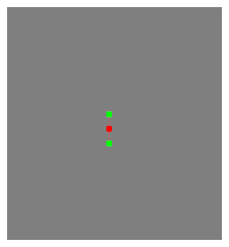 NOTE Only one set of handles will appear, but this is because all points are in the same position.
 - In the Camera view toolbar, click on
-
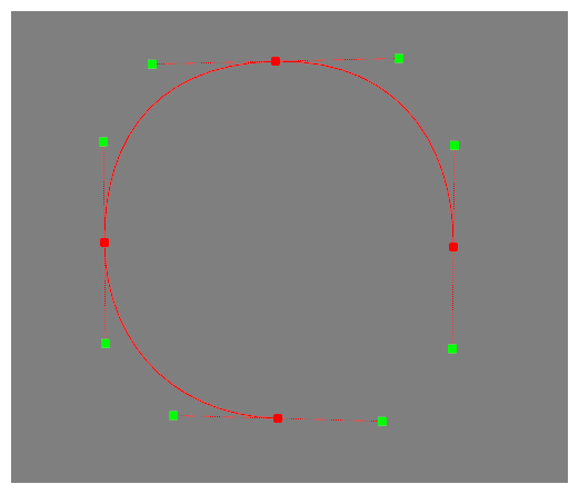
Drag each point out and form the desired shape. If you are working with Shape Curve nodes, manipulate the Bezier handles for each point to obtain the desired curves.
-
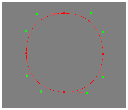
You may notice that there is no contour linking the last point in the chain to the first point. To fix this, In the Node View, click on the
 Layer Properties button for the lowest Shape Line or Shape Curve node in the chain. Then, in its Layer Properties dialog, check the Close Shape Contour option.
-
Repeat steps 4 through 9 to create another shape inside the first one.
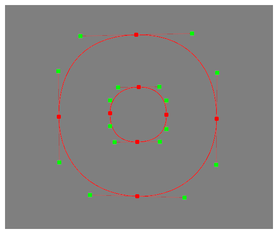 NOTE You can connect several chains of Line Shape or Curve Shape nodes to the Shape Render node to give it several shapes.
 -
Select all the points of the inner shape by holding the Shift key and clicking on each point. When the points are selected, they will be highlighted in purple.
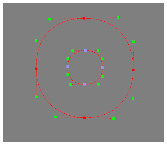
-
While holding the Alt key, click on one of the selected points and drag it upwards. This will move the points closer towards the camera. As a result, the points will appear larger to give you a visual indication of their position on the z-axis.
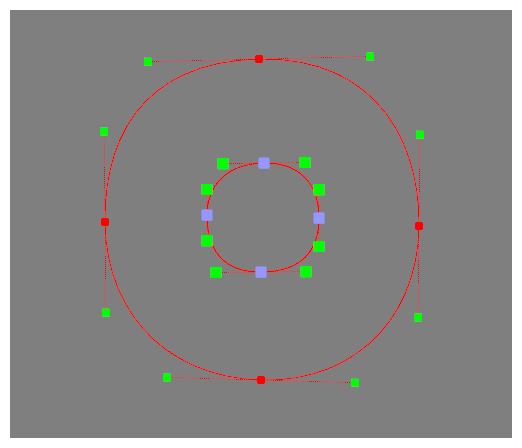
-
In the toolbar at the bottom of the Camera view, click on the
Render View button to preview the high map generated by your shapes. There should be a gradient going from the contour of the outer shape to the contour of the inner shape. The lightness of each pixels is representative of its height in the height map.
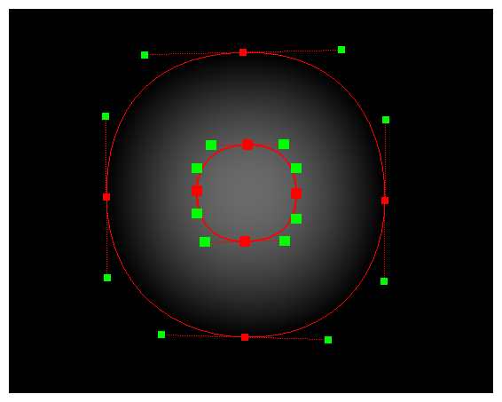
- The Shape Render is best used to provide a Height Map for a Volume Object node—see
- The output of the Shape Render node is in fields, which means that the differences when adjusting the height of certain points may be difficult to discern. For a more legible preview, you can connect the Shape Render node to the Height Map port of a Volume Object, then preview the resulting surface map instead—see Previewing the Surface Map.