Planar Region

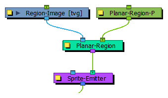
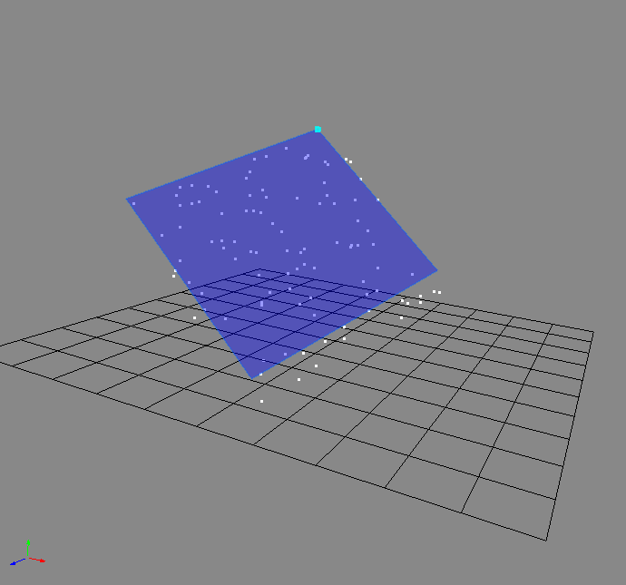
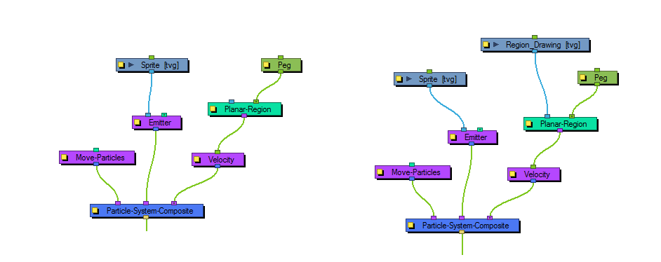
Like the 3D region, this determines a region that you can use as a source or as a bounce plane, but instead of a 3D region, it's a 2D plane. Connect a peg to the right in-port to adjust the position of the plane.

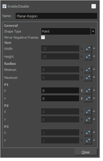
Planar Region Properties

Parameter Description
Name Allows you to change the name given to the node.
Shape Type

Allows you to define the type of shape of the plane.

The following shape types are available:

  • Basic shape types:

    Those are simple shapes that are defined by a small set of coordinates.

    Depending on the type of shape you choose, the parameters below will be available or greyed out so that you can adjust the actual shape of the plane. However, you can also adjust the shape of the plane visually using the Transform tool. To do that, you must display the Planar-Region’s control by selecting the Planar-Region node in the Node view, then doing one of the following:

    • In the Camera view toolbar, click on Show Control .
    • From the top menu, select View > Show > Control.
    • Press Shift + F11.

    The following basic shape types are available:

    • Rectangle: A rectangle. You can set the size of the rectangle using the Width and Height parameters.
    • Disc: A circle with a circular hole in the middle. You can adjust the disc’s size by changing the Radius parameters, where Minimum is the radius of the hole and Maximum is the radius of the disc.

    • Triangle: A triangle. The coordinates of all three points can be set in the X and Y fields under P1, P2 and P3.

    • Line: A line. The coordinates of the two points defining the lines can be set in the X and Y fields under P1 and P2.

    • Point: A single point. Its coordinates can be set in the X and Y fields under P1.

  • Image shape types:

    Those shape types use an input image to define the plane. To use them, connect a single drawing layer to the left input port of the Planar-Region node.

    The two following image shape types are available, and produce slightly different results:

    • Image: With this option, the input image shape is used to determine the planar region, but its alpha is also used to modulate the density of the particles. For example, semi-transparent areas will have less particles than fully opaque ones.

      However, with this option, the region is cropped to the input drawing’s 4:3 grid. By default, this grid is shrunk to fit the vertical resolution of the scene. Hence, with this option, the particles will be cropped by a frame that has a 4:3 aspect ratio and will not reach all the way to the left and right edges of the camera frame. To work around this, you can use the Vector Drawing option, or set your scene’s field of view to Horizontal Fit—see Scene Settings Dialog Box.

    • Vector Drawing: This uses the entire shape of the input drawing to define the planar region, without accounting for the drawing’s grid. As a side effect, an input drawing that is considerably bigger than the camera frame will result in more sparse particles. This option ignores the alpha of the input image, and only uses its shape.
Mirror Negative Frames Mirrors the input peg transformation to generate positions for frames before the scene begins.
Size

Width: The width of a rectangular shape.

Height: Adjust the height of a rectangular shape.

Radius

Minimum: The radius of the hole for a disc shape.

Maximum: The radius of the whole disc for a disc shape.

P1

X: The X position of Point 1. Point 1 could refer to the point on a triangle, line, or point.

Y: The Y position of Point 1.

P2

X: The X position of Point 2. Point 2 could refer to the point on a triangle or line.

Y: The Y position of Point 2.

P3

X: The X position of Point 3. Point 3 refers to a point on a triangle.

Y: The Y position of Point 3.