The Multi-Points Constraint translates, rotates and scales a drawing to make it follow the pivots of the pegs that are connected to it. Optionally, it can also apply a perspective transformation on the element.
Connection
The Multi-Points Constraint node must be connected to at least two Peg nodes, and can be connected to as many Peg nodes as needed. The pivot point of each peg will define the resting position of one of the points used to transform the drawing connected under it. When one of the pegs is moved, the Multi-Points Constraint will transform the drawing so that it follows the pivot point of that peg.
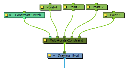
Only the position of the pegs is considered by the Multi-Point Constraint. The position of the peg connected to the rightmost input port on the Z-axis will be applied to the element.
Optionally, the Three-Points Constraint node can be connected to a Constraint-Switch, which can be used to reduce the effect of the Three-Points Constraint node on the element it is connected by setting its Active parameter between 0 and 100.
Controls
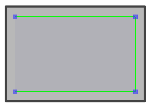
When the controls of the Multi-Points Constraint are displayed, the position of the points are displayed with blue squares linked by a green line.
These points are only a visual representation and cannot be manipulated.
- In the Tools toolbar, select the Transform tool or press Shift + T.
- Do one of the following:
- Select one of the pegs the Three-Points Constraint is connected to, then move the peg by clicking and dragging the centre point in the Camera view.
- In the layer properties of the element, disable the Animate Using Animation Tools option. Then, select the element, and click and drag the element near one of the points. The point that is the closest to the mouse cursor will be automatically selected and moved.
Optionally, the leftmost input port of a Multi-Points Constraint node can be connected to a Constraint-Switch, which can be used to reduce the effect of the Multi-Points Constraint node on the element it is connected by setting its Active parameter between 0 and 100.
| Parameter | Description |
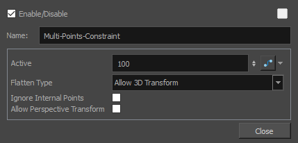
| Active |
The percentage of influence the constraint has on its child element. If set to 100, the element will follow the points closely. If set to 0, the element will not be affected by the constraint. If a Transformation Switch node is connected to the Multi-Points Constraint node, the Active parameters of the Transformation Switch and the Multi-Points Constraint nodes will be multiplied together. |
| Flatten Type |
This parameter defines what happens if one of the pegs defining the constraint points is moved on the Z-axis:
NOTE This projection is based on the position of the primary point peg on the Z-axis. Hence, if the three pegs are on a different position on the Z-axis, there may be a perceived offset between the position of the non-primary points and their effect on the element.
|
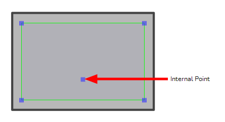
| Ignore Internal Points |
If enabled, internal points will be ignored by the Multi-Point Constraint. The envelope used to transform the element is always a convex shape. If any point connected to the Multi-Points Constraint is not an extreme point in its resting position, it is considered an internal point.
|
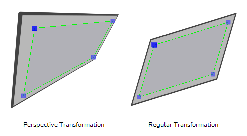
| Allow Perspective Transform |
If this option is enabled, the Multi-Point Constraint node will apply a perspective deformation to the drawing instead of scaling, rotating and skewing the drawing to try to make it track the points.
|