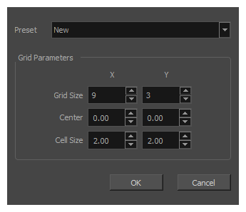
When you launch the Grid Wizard, you are first prompted with the Grid Parameters dialog, in which you can set up the size of the grid, but also its centre position as well as the size of each cell in the grid.
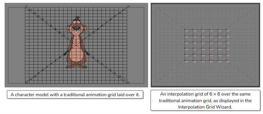
The coordinates used for the centre position and the cell size are in fields, and are based on the field grid used to position objects in your scene. This is a traditional, 12 fields, 4:3 animation grid, with its centre coordinates being (0, 0), and with horizontal coordinates incrementing from left to right, and vertical coordinates incrementing from bottom to top. You can see how a traditional animation grid, when laid out on your scene, corresponds to the grid displayed in the Grid wizard in the following side by side comparison:
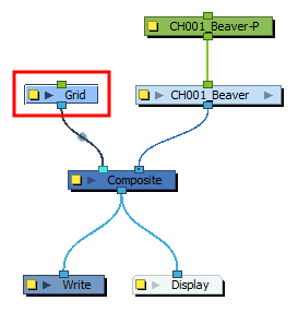
To lay out an animation grid over your scene, simply add a Grid node and connect it to your scene's main composite
When you display a 2D point widget created with the Grid Wizard, it will appear somewhere inside the area covered by the grid it was created with. When you move it around, it will be able to move up to the edges of that grid. Hence, by adjusting the centre position and cell size of your grid before you create it, you can make it so the position of the part of your character rig you want to control closely matches the position of the 2D point as you move it.
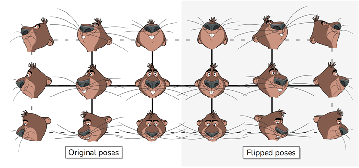
For example, if we want to create an grid of the following set of poses, we need to create a grid of 6 vertical poses × 3 horizontal poses:
At the default centre position (0, 0) and cell size (2 fields × 2 fields), a grid of 6 × 3 poses would occupy this area of the scene:
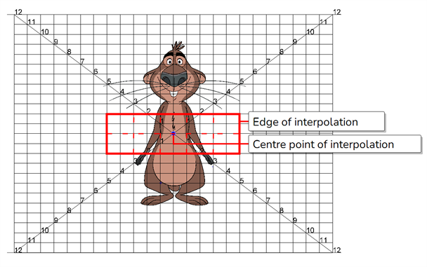
An animator would have to move the 2D point widget in this rectangular area to control the direction in which the character is looking. This is not intuitive. What would be preferable is a grid like this:
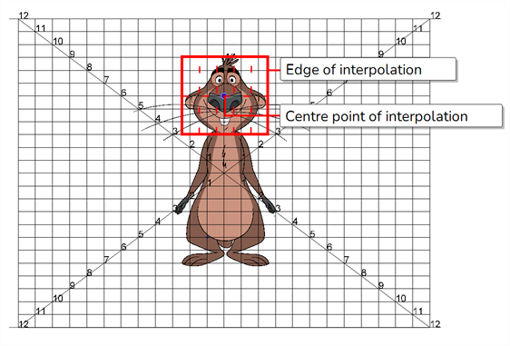
To obtain such a result, you would first need to figure out the ideal centre position of the grid. In this case, it is the centre of the character's nose which, according to the grid, is in the middle on the horizontal axis, and 6 fields north on the vertical axis, making its exact coordinates (0, 6).
Then, you would need to adjust the cell size to obtain a less rectangular, more square-like grid. In this case, the default cell size was set to 1 horizontal field and 3 vertical fields, or 1 field × 3 fields. Although this makes vertical rectangular cells, since we have 6 columns for 3 rows, the resulting grid is nearly square-shaped.
By calculating and using precise coordinates, you can even create a 2D point master controller that appears to be attached to a specific articulation of your character. For example, let's say you are working with the four arm poses, and you want to create a 2D point widget that will be attached to the wrist:
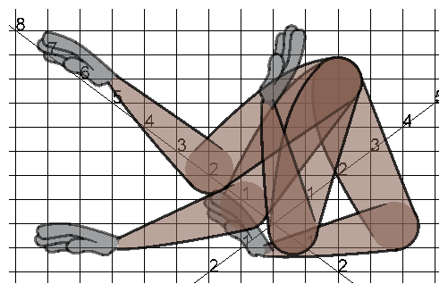
You could spread those four wrist poses at the corners of a rectangle, grid, like so:
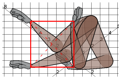
A rectangle can be represented by a simple grid of 2 poses x 2 poses, which has a single cell. The size of ts cell size would determine the size of the entire grid. Hence, you would simple have to figure out the size and centre coordinates and size of this rectangle, in fields, and create an gird of 2 x 2 poses, positioned at the centre of this rectangle, and with a cell size that is the size of this rectangle. In this case, the rectangle is 6 x 8 fields, and its centre is at (2.5, 2.5).