Adjusting Colour Levels
You can adjust the colour levels on an imported bitmap image or scanned image using the Colour Levels node.
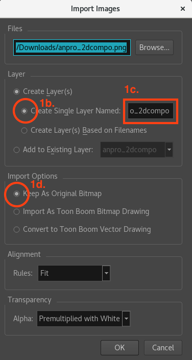
- In the Top menu, select File > Import > Images.
- Select the Create Single Layer Named option under the Create layer(s) section.
- Define the name for that Drawing layer.
- Select the Keep As Original Bitmap option under the Import Options section.
- Click on the OK button to validate.
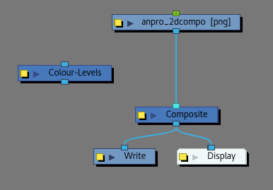
- Drag from the Node Library view to the node view a Colour Levels node.
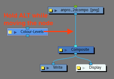
- Select the Colour Levels node and, while holding ALT (or Cmd on Mac), move it near the cable link linking the sketch drawing node to the Composite node.
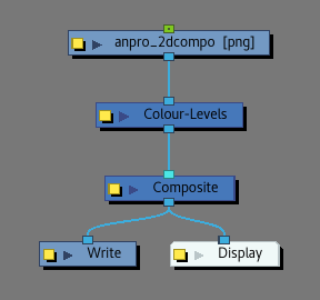
This will connect it directly to the cable under the sketch drawing node.
- From now on, enable the Render View mode as the following effects and parameters are not visible in OpenGL mode.
- Open the Colour Levels node’s Layer Properties to modify the parameters.
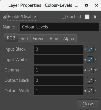
- In the RGB tab:
- Increasing the value of the Input Black parameter will make the darkest parts of the drawing closer to black
- Decreasing the values of the Input White parameter will make the lightest parts of the drawing closer to white
- Modifying the values of the Gamma parameter to a higher value than one will increase the value of dark colours proportionally to their actual values, increasing the contrast between them and making them lighter.
- Increasing the Output Black level will make the black pixels in the drawing appear lighter. All other pixels in the drawing will also appear lighter, but the closer to white they are, the less lightness is added to them.
- Decreasing the Output White level will make the white pixels in the drawing appear darker. All other pixels in the drawing will appear darker, but the closer to black they are, the less darkness is added to them.
NOTEThe same logic is kept for all parameters within each channel tab, but instead of modifying all the channels at the same time like in the RGB tab, the other one will modify only one channel at a time.
Example with random values for some channels:
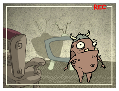
Original
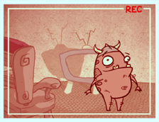
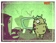
Red Green Blue
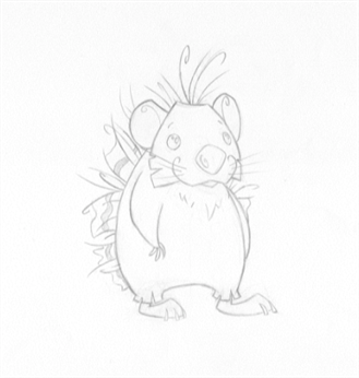
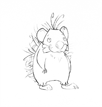
Before After
@ 2018 hedgehog by Clemence Dufresne
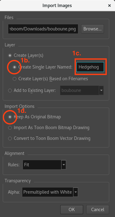
- In the Top menu, select File > Import > Images.
- Select the Create Single Layer Named option under the Create layer(s) section.
- Define the name for that Drawing layer.
- Select the Keep As Original Bitmap option under the Import Options section.
- Click on the OK button to validate.
- Drag from the Node Library view to the node view a Colour Card node
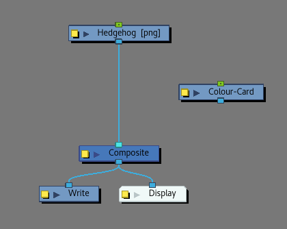
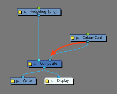
- Connect the Colour Card on the right side of the sketch drawing port on the Composite node.
The Colour Card will make it easier to clean up the drawing and see the remaining grey spots when playing with the Colour Levels.
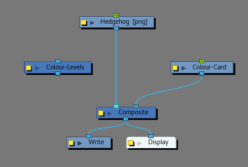
- Drag from the Node Library view to the node view a Colour Levels node.
- Select the Colour Levels node and, while holding ALT (or Cmd on Mac), move it near the cable link linking the sketch drawing node to the Composite node.
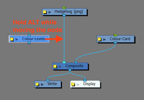
This will connect it directly to the cable under the sketch drawing node.
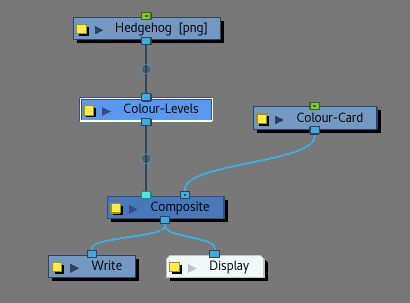
- From now on, enable the Soft Render and keep working with it since the next effects don’t appear in OpenGL.
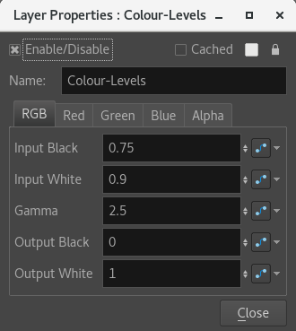
- Open the Colour Levels node’s Layer Properties to modify the parameters.
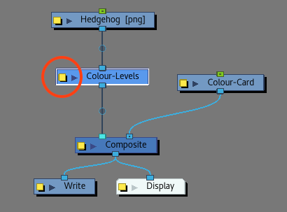
The Colour Levels node will be useful to reduce the amount of greys and to clean up the image.

- In the RGB tab:
- Increasing the value of the Input Black parameter will make the darkest parts of the drawing closer to black
- Decreasing the values of the Input White parameter will make the lightest parts of the drawing closer to white
- Modifying the values of the Gamma parameter to a higher value than one will increase the value of dark colours proportionally to their actual values, increasing the contrast between them and making them lighter.
- Drag from the Node Library view to the Node view a Negate node.
- Connect the Negate node under the Colour Levels node.
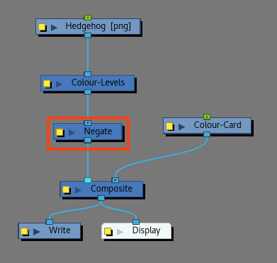
No need to modify its Layer Properties. Values can be kept as is.
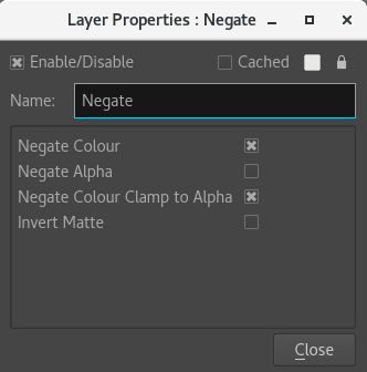
The Negate node will make the line brighter where it exists, and darker where it doesn't. So the luminance will be able to pick it up for alpha.
- Drag from the Node Library view to the Node view a Channel Swap node.
- Connect the Channel Swap node under the Negate node.
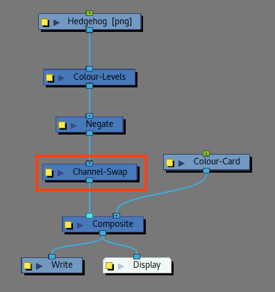
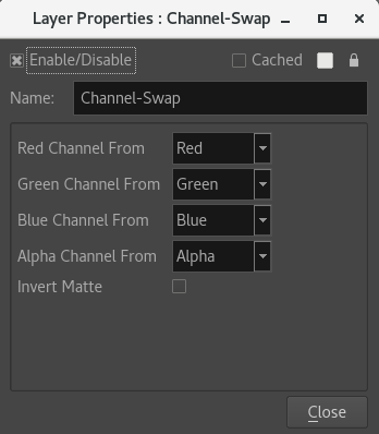
- Open the Channel Swap node’s Layer Properties to modify its parameters.
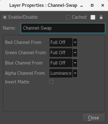
By Turning all RGB channels except the Alpha to black and using the luminance option to be the alpha. It is now possible to have a black drawing with an invisible background.
- Modify the Red Channel to: Full Off
- Modify the Green Channel to: Full Off
- Modify the Blue Channel to: Full Off
- Modify the Alpha Channel to: Luminance
NOTE
- By modifying a channel to “Full Off”, it changes the channel to Black.
- By modifying a channel to “Lumiance”, it changes the channel to White.