The Two-Points Constraint translates, rotates and scales a drawing to make it follow the pivots of the two pegs connected to it. Hence, it allows an animator to position an element (for example, a limb) by moving the two points at its extremities (the articulations).
Contrary to Three-Points Constraint and Multi-Points Constraint nodes, Two-Points Constraint can automatically stretch and squash the element they are connected to depending on the distance between the two points. This effect can be fine-tuned in the layer properties of the Two-Point Constraint node.
Connection
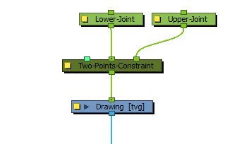
The Two-Points Constraint node must be connected to two Peg nodes. The pivot point of each peg will define the resting position of one of the points used to transform the drawing connected under it. When one of the pegs is moved, the Two-Points Constraint will transform the drawing so that it follows the pivot point of that peg.
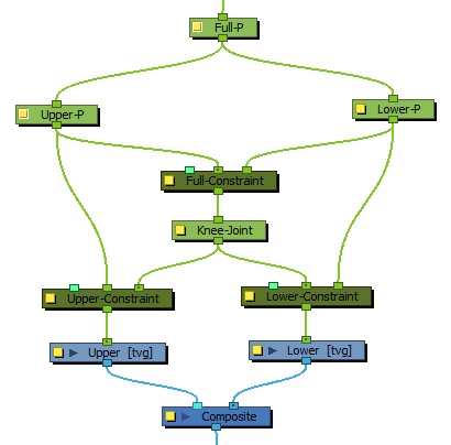
It is possible to rig multiple Two-Points Constraint nodes together in order to connect adjacent parts of a character rig by their articulation. For example, the upper and lower part of an arm or a leg could be rigged together in the following fashion, to allow the animator to manipulate them by their articulations:
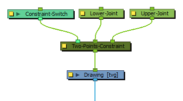
Optionally, the leftmost input port of a Two-Points Constraint node can be connected to a Constraint-Switch, which can be used to reduce the effect of the Two-Points Constraint node on the element it is connected by setting its Active parameter between 0 and 100.
Controls
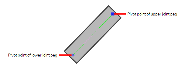
When the controls of the Two-Points Constraint are displayed, the position of the two points are displayed with blue squares linked by a green line.
These points are only a visual representation and cannot be manipulated.
- In the Tools toolbar, select the Transform tool or press Shift + T.
- Do one of the following:
- Select one of the pegs the Two-Points Constraint is connected to, then move the peg by clicking and dragging the centre point in the Camera view.
- In the layer properties of the element, disable the Animate Using Animation Tools option. Then, select the element, and click and drag the element near one of the two points. The point that is the closest to the mouse cursor will be automatically selected and moved.
Properties
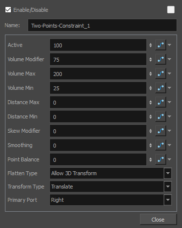
| Parameter | Description |
| Active |
The percentage of influence the constraint has on its child element. If set to 100, the element will follow the two points closely. If set to 0, the element will not be affected by the constraint. If a Transformation Switch node is connected to the Two-Points Constraint node, the Active parameters of the Transformation Switch and the Two-Points Constraint nodes will be multiplied together. |
| Volume Modifier |
Defines how much the Two-Points Constraint node should preserve the width of the child element when the distance between the points causes it to stretch or squash. If set to 100, the width of the element will increase when squashed and decreased when stretched based on the Volume Max and Volume Min parameters. If set to 0, the element will always have the same width regardless of how much it is stretched or squashed. The value can be set to a number between 0 and 100 to reduce the effect of the volume modifications, to a number above 100 to increase it, or to a negative number to reverse the volume modification logic. |
| Volume Max |
The maximum width of the element when squashed. This value represents a percentage of the element's original width. If set to 0, no minimum width will be applied. |
| Volume Min |
The minimum width of the element when stretched. The value represents a percentage of the element's original width. If set to 0, no maximum width will be applied. |
| Distance Min |
The minimum distance between the two points. If the points are brought closer together than their minimum distance, the element will stop transforming. This value represents a percentage of the distance between the two points when in their respective resting positions. |
| Distance Max |
The maximum distance between the two points. If the points are brought farther from each other than their maximum distance, the element will stop transforming. This value represents a percentage of the distance between the two points when in their respective resting positions. |
| Skew Modifier | When set to 0, the element is rotated to follow the two points. If set to 100, the element will skew to follow the two points. If set between 0 and 100, the element will be transform with a combination of rotation and skewing to follow the two points. |
| Smoothing |
When the two points are moved away from each other and reach their maximum distance, this value will adds an extra buffer of distance that the two points can reach before the element stops stretching. In this buffer, the way the element stretches is tapered, making it stop stretching smoothly instead of abruptly. This value represents a percentage of the distance between the two points when in their respective resting positions. |
| Point Balance |
This parameter comes in effect when the two points are being moved at a distance exceeding their maximum distance. If set to 0, the element will stop stretching and remain locked against the primary point. If set to 100, the element will stop stretching and remain locked against the second point. If set to a value between 0 and 100, the element will be moved between both points, at a distance from the primary point that is proportional to this setting. |
| Flatten Type |
This parameter defines what happens if one of the pegs defining the constraint points is moved on the Z-axis:
NOTE This projection is based on the position of the primary point peg on the Z-axis. Hence, if the two pegs are on a different position on the Z-axis, there may be a perceived offset between the secondary point and its effect on the element.
|
| Transform Type |
By default, only the position of the points is used to transform the element. Since those points are defined by pegs, these pegs can also be subjected to scale, angle and skew transformations that would be normally ignored by the Two-Points Constraint node. This parameter can be used to apply the other transformations done on the peg of the primary point on the element, rather than ignoring them.
|
| Primary Port |
Defines which one of the ports, and hence, which one of the pegs the node is connected to, is used to define the primary point, leaving the other port for the secondary point. The primary point affects the other parameters in several ways:
|