T-COMP2-005-002
The Composite-Generic node is a customizable effect that can be used to fit scenarios where the colours and alpha values of elements must be processed and combined in very specific ways. It can be configured to reproduce the effects of a Tone or Highlight node, or many of the blending effects available in the Blending node, but it offers significantly more control the way the effect is applied.
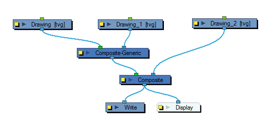
Among other things, the Composite Generic can be configured to apply a simple blending effect. However, contrary to the Blending node, the Composite Generic node does not composite its input image onto every element that is behind it in the scene. Rather, it composites one image, connected to its left input port, onto another, connected to its right input port. The resulting composited image is then composited onto the scene as normal.
Another interesting capability of the Composite Generic node is that it can use the colours and the alpha of either or both the overlay and the underlay image to make the output image. With the Colour Operation and Alpha Operation parameters, the colours and alpha values can be composited in different ways.
Connection
The Composite Generic node has two input ports and one output port. It will composite the image connected to its left input port (the overlay) onto the image connected to its right input port (the underlay) based on its properties, and will output the resulting composited image.
Properties
| Parameter | Description |
| Enable/Disable |
Allows you to enable or disable the node. When disabled, a node has no visible effect on the rendered image, nor on the preview in the Camera, |
| Colour Swatch |
Sets the colour of the layer in the Timeline view |
| Name | Allows you to enter a name for the node. |
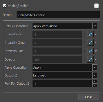
| Colour Operation |
The algorithm used to composite the colours of the underlay and overlay images together. Note that the way the alpha of the under and overlay images are composited depends entirely on the Alpha Operation parameter. NOTE
Some of the available blending modes have a BETA or Legacy variant to them.
In the following descriptions, the underlay image is the image connected to the right input port of the node, and the overlay image is the image connected to the left input port of the node. Right: Only outputs colour values from the underlay image and ignores colour values from the overlay image. Left: Only outputs colour values from the overlay image and ignores colour values from the underlay images. Apply With Alpha: Composites the overlay pixel onto the underlay pixel proportionally to its alpha value. This is the standard composition technique when layers are connected to a composite. Apply Tone Highlight: Applies the colour of overlay pixel the same way a Tone or Highlight effect would apply its colour to the underlay pixel. Apply Add / Apply Add Legacy:Adds the colour values of each channel in the overlay pixel and the underlay pixel. For example, adding two dark grey pixels with a value of 100 in each channel will result in a light grey pixel with a value of 200 in each channel. Likewise, if one of the pixels is red and the other is green, the resulting pixel will be yellow. Apply Matte For Overlay: Multiplies the colour values of the underlay image with the transparency ratio of the overlay image. This uses the overlay image as a "matte" to remove colours from the underlay image. You can then combine the resulting image with the colour values of the other image element by connecting this Composite Generic node to another Composite Generic node with its Colour Operation parameter set to Apply Overlay Into Matte. This is useful if the matte of the overlay and the colours of the overlay are to be stored in separate images. Apply Overlay Into Matte: Multiplies the colour values of the overlay by the alpha values of the underlay image, then adds the resulting colour to the colour values of the underlay image. This is useful if you have darkened an area of an underlay with a matte using a different Composite Generic with its Colour Operation parameter set to Apply Matte for Overlay. This parameter will take the colours from the overlay and apply them on the area darkened by the matte. Apply Transparency: Multiplies the colour values of the underlay image with the transparency ratio of the overlay image. This setting is designed to be combined with the Apply Transparency Matte alpha operation. However, it is technically the same as Apply Matte For Overlay. Apply Multiplicative Tone: Multiplies the value of each channel in the underlay pixel with the value of each channel in the overlay pixel, treating those values as ratios. Multiplying anything with black will result in black, and multiplying anything with white will leave the colour unchanged. Multiply Colours: Multiplies the value of each channel in the underlay pixel with the value of each channel in the overlay pixel, treating those values as ratios. Multiplying anything with black will result in black, and multiplying anything with white will leave the colour unchanged. Divide Colours / Divide Colours Legacy: For each channel, this divides the value of the underlay pixel by the value overlay pixel. Both values are treated as ratios, so the resulting colour is brighter. A white overlay pixel will leave the underlay colour unaffected, and a black overlay pixel will always result in white. Lighten / Lighten Legacy / BETA Lighten: For each channel, uses the value that is the brightest between the underlay pixel and the overlay pixel. Softlight / Softlight Legacy / BETA Softlight: Each channel of the overlay pixel lightens or darkens the corresponding channel of the underlay pixel on a softer scale. The effect is proportional to how dark or bright the overlay pixel is, but inversely proportional to how dark or bright the underlay pixel is. Hardlight / Hardlight Legacy / BETA Hardlight: This screens overlay pixels with a value above 50% onto underlay pixels, and multiplies overlay pixels with a value below 50% onto underlay pixels. The brighter the overlay pixel is, the more intense the screen effect will be. The darker the overlay pixel is, the more intense the multiplying effect will be. Blending any colour with white or black will result in white or black, and blending a colour with plain grey will leave the colour unchanged. Overlay / Overlay Legacy / BETA Overlay: Like hardlight, exept it screens or multiplies the underlay pixel over the overlay pixel, based on the value of the underlay pixel. Linear Light: This linear dodges overlay pixels with a value above 50% onto underlay pixels, and linear burns overlay pixels with a value below 50% onto underlay pixels. The brighter the overlay pixel is, the more intense the linear dodging effect will be. The darker the overlay pixel is, the more intense the linear burning effect will be. Pinlight: For each channel, if the overlay pixel's value is above 50%, use the lightest pixel between the underlay and overlay pixels. If the overlay pixel's value is below 50%, use the darkest pixel between the underlay and overlay pixels. Vividlight: This colour dodges overlay pixels with a value above 50% onto underlay pixels, and colour burns overlay pixels with a value below 50% onto underlay pixels. The brighter the overlay pixel is, the more intense the colour dodging effect will be. The darker the overlay pixel is, the more intense the colour burning effect will be. Exclusion: Adds the overlay and underlay pixel, then subtracts the multiplied value of both pixels twice. This results in an effect similar to Difference, except that while the Difference mode produces consistently high contrast pixels, the contrast of the resulting pixels with the Exclusion mode is proportional to how dark or bright the overlay pixels are. Dodge: Lightens each channel in the underlay pixel with the brightness value of the corresponding channel in the overlay pixel, by decreasing the contrast of the underlay pixel. Burn: Darkens each channel in the underlay pixel with the darkness value of the corresponding channel in the overlay pixel, by increasing the contrast of the underlay pixel. Hue: Outputs a colour with the luminosity and saturation of the underlay pixel and the hue of the overlay pixel. Saturation: Outputs a colour with the luminosity and hue of the underlying colour, and the saturation of the source colour. Colour: Outputs a colour with the hue and saturation of the overlay pixel, and the luminosity of the underlay pixel. The overlay layer can hence be used to "colourize" the underlay layer. Luminosity: Outputs a colour with the hue and saturation of the underlay pixel and the luminosity of the overlay pixel. This is the reverse of the Colour blending mode. |
| Intensity Red / Green / Blue |
The factor by which to multiply each channel in the overlay image. You can set this to a value between 0 and 1 to reduce the impact of the corresponding channel in the overlay image, or to a value above 1 to increase it. NOTE These parameters are only available when a BETA Colour Operation is selected.
|
| Opacity |
A value between 0 and 100 determining the opacity level of the overlay image when composited onto the underlay image. NOTE This parameter is only available for certain Colour Operation settings.
|
| Alpha Operation |
Right: The transparency of the output image is based on the alpha values of the underlay image only. Left: The transparency of the output image is based on the alpha values of the overlay image only. Apply: Combines the alpha values of the overlay and underlay image. When combined with the Apply with Alpha colour operation, this results in standard alpha-based compositing. Add: The alpha value of each pixel is the sum of the alpha value of the underlay pixel and of the alpha value of the overlay pixel. Subtract: The alpha value of each pixel is based on the alpha value of the underlay pixel subtracted by the alpha value of the overlay pixel. Apply Transparent Matte: The alpha value of each pixel is based on the alpha value of the underlay pixel, multiplied by the transparency of the overlay pixel, effectively multiplying their transparency. Black: Outputs every pixel as fully transparent of both the output as fully transparent, leaving behind only the effect of premultiplication of their colour values onto the rendered image. White: Sets the matte of the entire output image to white, so that it is fully opaque. The bounding box of the output image will be filled with black and semi-transparent pixels will be mixed with black. |
| Output Z |
Leftmost: Indicates that the Z value for the output image will be taken from the node in the left port. Rightmost: Indicates that the Z value for the output image will be taken from the node in the right port. Backmost: Indicates that the Z value for the output image will be taken from the image that is the farthest back in the scene. Frontmost: Indicates that the Z value for the output image will be taken from the image that is closest to the front of the scene. Portnumber: Indicates that the Z value for the output image will be taken from the node in the selected port. Enter the appropriate port in the Port for Output Z field. |