Normal Map Node
The Normal Map node lets you centralize all Volume Object nodes and chisel out the shading 3D geometry (bevel height, smoothing, carving, etc.). It could be described as carving a bas relief. You only need one Normal Map node per light shading effect and, in general, only one per scene.
A normal map can be used to create other effects. If you're are working with an OpenFX plugin or other plugin requiring a normal map, you can use the Normal Map Converter node to translate the Harmony normal map to a format supported by your plugin. The Normal Map Converter node has been optimized to work with GenArts® plugins, but you also have the ability to use it on custom plugins.
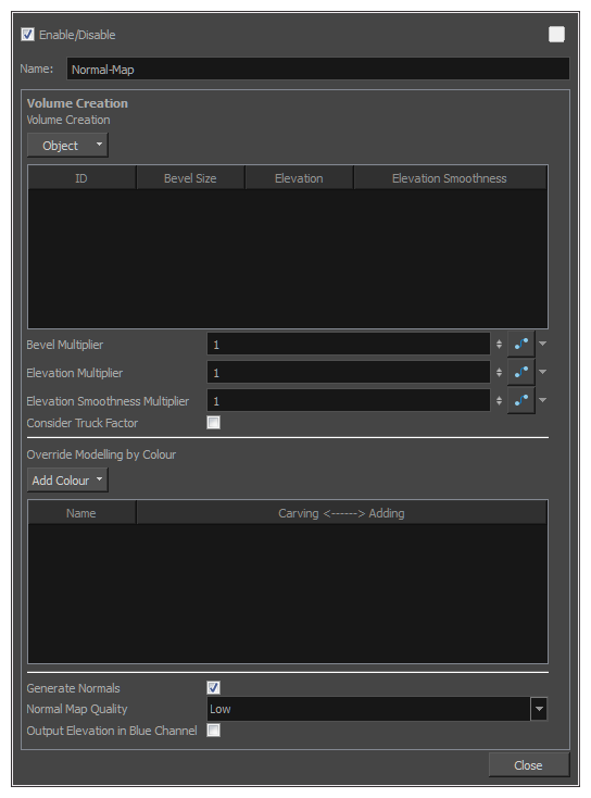
Normal Map Properties
| Parameter | Description |
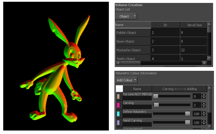
| Volume Creation |
Lists all the different volume object IDs are listed. This is where you can define the basic volumetric shape of each Volume Object node connect to the Normal Map. |
| Object |
Let you add or remove Volume Object nodes that are connected to the Normal Map node. Add All Defined Objects: Adds all Volume Object nodes connected to the Normal Map node. Remove Selected Objects: Removes all Volume Object nodes from the Volume Creation list. |
| Name |
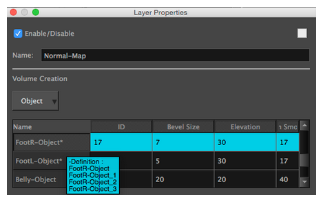
The name that was previously set ineach Volume Object node. This information can be really helpful when there are many volume objects listed. With a good name, it is easy to discover what the ID number is related to. When you hover over this column, a tooltip appears listing all volume objects with the same ID. In the following image, the tooltip indicates that three copies were made from FootR-Object. By keeping the same name, you can easily see that each time you see a Volume Object named “FootR-Object”, the ID will be the same.
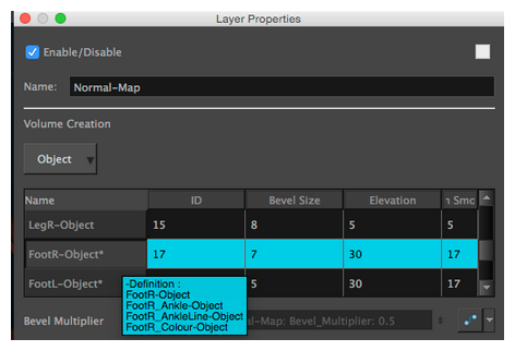
In the second example, a specific name was created for each volume object, even if they have the same ID. That way, it is easy to find a specific
|
| ID |
The identity number that was previously set in the volume object
|
| Bevel Size |
Defines the size of the bevel on the contour of all the drawings related to a specific ID number |
| Elevation |
Defines the elevation of a specific volume object. The higher the value, the more the volumetry of this Volume Object resembles a conical or pyramidal shape. |
| Elevation Smoothness |
Complementary to the Elevation column. Instead of keeping a conical or pyramidal shape, the shape will be smoothed to create a sphere or a bump shape. The edge will be round instead of sharp. |
| Bevel Multiplier |
A multiplier of the Bevel Size value in the board. This affects every object listed. |
| Elevation Multiplier |
A multiplier of the Elevation value in the board. This affects every object listed. |
| Elevation Smoothness Multiplier |
A multiplier of the Elevation Smoothness value in the list. This affects every object listed. |
| Consider Truck Factor |
Keeps the same ratio for the Light Shading system when the camera zooms in or out. This parameter cannot work properly if the size of the drawing, with a volume object |
| Override Modelling by Colour | |
| Add Colour |
Lets you add or remove any colour that will affect the Adding/ Carving options in the list beneath. When you select this button, each colour palette in the scene is listed and all their swatches are displayed. |
| Swatches |
The first column of the Override Modelling by Colour board is the Swatches. This column does not have a name. When you select a colour swatch from the Add Colour list, the colour swatch appears at the beginning of the list. |
| Generate Normals |
Activates or deactivates the generation of the Normal Map. |
| Normal Map Quality |
Lets you change the Quality of the Normal Map from low to high. |
| Output Elevation in Blue Channel |
When selected, the Elevation is calculated and appears in the soft render mode. When deselected, the object ID appears in the soft render mode. Because it is connected to the blue channel of a drawing, the result will only affect the blue channel. |