
Linking to 3D Movements
You can link 2D drawing layers, pegs, other 3D models and more to follow the movements of a part of a 3D model. To do this, you need to add a 3D Kinematic Output node to your 3D model setup in the Node view. More specifically, you need to link the 3D Kinematic Output node to both a specific 3D model subnode (part) and to the object that you would like to follow that subnode.
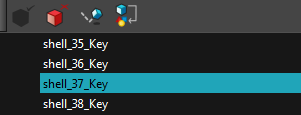
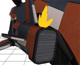
- In either the Camera, Perspective or 3D Graph view, select the part of the 3D model whose movements you would like followed.
- In the 3D Graph view, click on the 3D Graph view menu
 button and select Insert > 3D Kinematic Output.
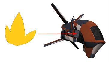
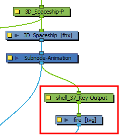
 - In the Node view, connect the top port of the object that you would like to follow to the bottom port of the 3D Kinematic Output node. In this example, a 2D drawing layer (fire) is connected.

If you are going to make the selection in the Camera or Perspective view, be sure to have the Transform tool selected. Click on your 3D model once to select the whole object, then click again to select the individual part.
OR
In the 3D Graph view toolbar, click on the Add 3D Kinematic Output ![]() button.
button.
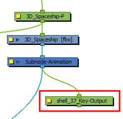
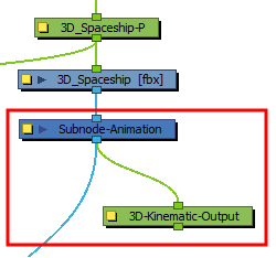
In the Node view, a 3D Kinematic Output node is added to your system. It is automatically given the name of the subnode + -Output.
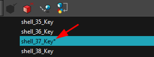
An asterisk appears beside the subnode name in the 3D Graph view list to indicate the connection of the 3D Kinematic Output node.
Any transformations made to the 3D model subnode will now also be applied to the drawing.
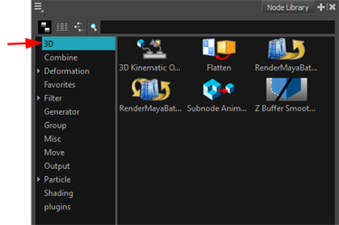
- In the Node Library, in the left menu bar, click on 3D.
- Drag and drop the 3D Kinematic Output node from the Node Library into the Node view.
- Connect the 3D Kinematic Output node under the Subnode Animation node of your 3D model.
- In either the Camera, Perspective or 3D Graph view, select the part of the 3D model whose movements you would like followed.
- In the 3D Graph view, click on the 3D Graph view menu button and select Edit > Copy Subnode Name. If this menu item is disabled, you may need to click on the highlighted subnode from the 3D Graph list and then try again. This usually occurs if you made your subnode selection in the Camera or Perspective view, instead of the 3D Graph view.
- In the Node view, open the Layer Properties of the 3D Kinematic Output node (yellow square).
- Right-click in the Subnode Name field and from the right-click menu, select Paste. Now the 3D Kinematic Output node knows which part of the 3D model to read.
- In the Name field, delete 3D-Kinematic from the node name, then paste again.
- In the Node view, connect the top port of the object that you would like to follow to the bottom port of the 3D Kinematic Output node. In this example, a 2D drawing layer (fire) is connected.
If you are going to make the selection in the Camera or Perspective view, be sure to have the Transform tool selected. Click on your 3D model once to select the whole object, then click again to select the individual part.
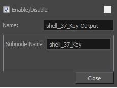
The name of the 3D Kinematic Output node should now be the name of the subnode + -Output. It is good practice to rename your 3D Kinematic Output node this way, so you know which subnode your object is following. This is especially true if you plan to add multiple 3D Kinematic Output nodes to your system.
An asterisk appears beside the subnode name in the 3D graph list to indicate the connection of the 3D Kinematic Output node.
Any transformations made to the 3D model subnode will now also be applied to the drawing.