About Nodes
Each element in the Node view is called a node. There are several different types of nodes:
|
Node |
Description |
|
| Drawing |
|
Transfers drawing information. |
| Effect |

|
Processes effects on drawings and transfers drawing information. |
| Input/Output |
|
Acts as the interface between each node and node system. |
| Transformation |

|
Controls the camera and element transformations over time. |
| Composite |

|
Combines multiple source images. |
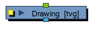
Drawing Node
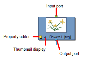
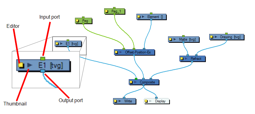
This is an example of an average node, a simple drawing node that represents a layer in the Timeline view. This node has an input port (top) that allows information to flow through it. It has an output port (bottom) that exports its information in a downward flow. On the left is a yellow button that displays the node's property editor, where you can adjust its parameters. Lastly, there is an arrow that displays a thumbnail of the node's contents at the current frame.
Write and Display Nodes
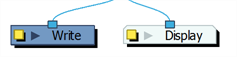
Both the Write and Display nodes do not have output ports. This is because the information that flows into them can go no further in the node system. The Write node records the images and renders the final output. The Display node captures the visual information and outputs it to the Camera, Perspective, Top, Side and Timeline views.
Composite Node
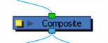
The Composite node combines multiple source images (drawing and effect nodes), including all transformations and effects, into a single bitmap or vector image for each frame.
The Composite node layers the images based on the composition order rule.
First, the Z-values of the elements are analyzed to determine depth. When multiple elements have the same Z-value, the Depth values in the drawing nodes are used. If the Depth values are also the same between elements, the composition order is determined by the cable order of nodes on the Composite node. By default, nodes connected to the right are rendered below those connected to the left. You can override this default in the Composite node editor
Effect Node
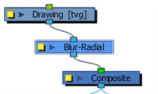
This is an example of a simple effect node taking a single image input and outputting a processed (blurred in this case) image.
An Effect node can often have two input ports. The right input port is for the drawing layer that is to be acted upon by this effect, while the left port is usually reserved for a matte.
Matte Input
A matte, also called mask, is the shape that will be used by the effect node to modify the original image (left input port). The effect will only be applied where the matte overlaps the original image. Sometimes the matte will act as a negative shape that the effect will exclude. This all depends on the nature and editing properties of the effect.
Transformation Ports
Some effects contain three input ports. If they are green, then they require a transformation (Peg, Quadmap, Quake, etc.) connection (coordinate and value information).
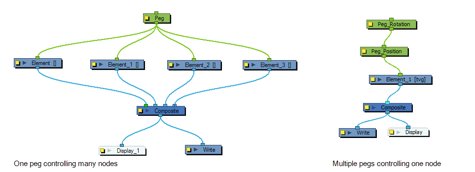
Peg Node
The Peg nodes control the transformation of elements (position, scale, skewing and rotation) over time. The green ports at the top and bottom of the node indicate that it accepts transformation information which can be passed on (inputs and outputs transformation information).
One peg can be used to control many different nodes or one node can accept more than one peg. In a situation like the latter, one peg might be used to modify the rotation, while the other is used to modify the position of the effect and then animated differently over time.