
Adapting the Scanner Hardware
Before using your scanner, you must make a few minor adjustments to make sure it can handle the special types of animation paper you will be using.
This section is divided as follows:
| • | Modifying the ADF Paper Chute |
| • | Mounting the Peg Bar and Calibrating the Scanner |
Modifying the ADF Paper Chute
On the ADF paper chutes of supported Fujitsu scanners, the paper guides are connected to each other by a cog wheel that keeps the paper guides and the drawings centred on the chute. Adjustments must be made to this type of Fujitsu scanner to avoid problems during the scanning process.
To compensate for the centred scanning on the ADF chute of Fujitsu scanners, do one of the following:
| • | Modifying the Scan.conf File for Centred ADF Scanning (requires no hardware modification) |
| • | Removing the Cog Wheel on Paper Chute |
| • | Adding a Paper Guide to Your ADF Scanner |
| • | Installing a Strip of Black Tape on the ADF Paper Path |
Modifying the Scan.conf File for Centred ADF Scanning
If you do not want to modify the ADF chute so that it is aligned towards the back of the scanner, you can use the leftOffset option in the Scan.conf file. To calculate the leftOffset option, consider that the paper chute on all supported Fujitsu scanners are 12 inches (2.54 cm) wide . If your paper is 10.5 inches (26.67 cm) wide, the difference between the chute and the paper is 1.5 inches (3.81 cm). Since this difference is distributed on both sides of the paper chute, the offset from either edge is 0.75 inches (1.90 cm). Therefore, the leftOffset option is 0.75 inches (1.90 cm).
The leftOffset option was added to this sample of the Scan.conf file:
host: scan-1
name: Fujitsu10.5
descr: The scanner to use for black & white and greyscale scans.
device: sc1;d5;l0
model: Fujitsu_fi4750C
defaultThreshold: 80
defaultResolution: 200
registrationStrictness: Loose
leftOffset: 0.75
You can add additional entries in the Scan.conf file to support paper of different sizes. For example:
host: scan-1
name: Fujitsu8
descr: The scanner to use for black & white and greyscale scans.
device: sc1;d5;l0
model: Fujitsu_fi4750C
defaultThreshold: 80
defaultResolution: 200
registrationStrictness: Loose
leftOffset: 2
Removing the Cog Wheel on Paper Chute
If you don't want to modify the Scan.conf file, you can remove the cog wheel so the paper guides can slide independently. This allows you to position the paper guide closest to the back of the scanner as far as it can go towards the back of the scanner. You can then slide the other paper guide up to meet the bottom edge of the stack of drawings to keep them aligned.
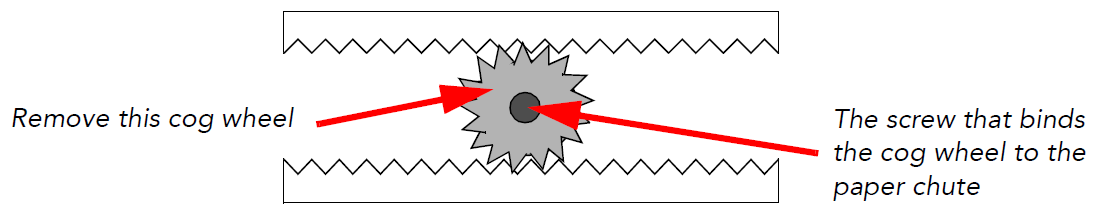
- Remove the paper chute from the scanner.
- Remove the screw that attaches the cog wheel to the paper chute.
After you remove the cog, the paper guides should be able to slide independently of each other.
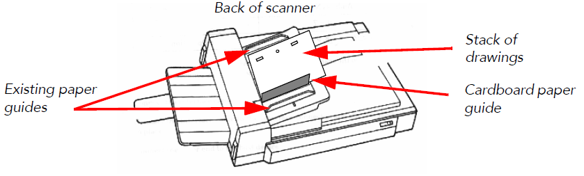
Adding a Paper Guide to Your ADF Scanner
Instead of removing the cog wheel on the ADF paper chute, you can make a paper guide to place between the existing paper guides to keep the stack of drawings in the proper alignment in the paper chute.
To perform this procedure, you will need the following materials:
| • | A paper guide made of cardboard, a block of wood, or similar material. |
| • | Adhesive tape to secure the paper guide to the paper chute. |
- Open the ADF paper guides to their widest position.
Place the paper guide closest to the back of the scanner as far out as it can go (toward the back of the scanner).
If you did not remove the cog wheel, this will make for a very wide paper chute, wider than most of your animation paper.
Now you must create an intermediate paper guide to hold your drawings in place.
- Place a stack of drawings in the paper chute so that they are touching the back paper guide. Make sure the back paper guide is as far back as it can go.
- Position the paper guide you created to secure the other edge of the paper stack.
- Secure the paper guide with tape.
Installing a Strip of Black Tape on the ADF Paper Path
When you scan drawings with the Scan module, drawings on paper become digital images in the Harmony system. These digital images must be properly aligned during the scan process to ensure that the animation flows smoothly from frame to frame in the final output.
| • | If you want to scan many drawings using the ADF chute on your scanner, you must use the Optical Registration option in the Scan module to automatically align your drawings. |
When you select the Optical Registration option, the Scan module identifies the peg holes to align the drawings.
You can also use the Optical Registration option if you want to manually scan a drawing on the flatbed part of the scanner.
| • | If you have a peg bar attached to your scanner, you don't have to use optical registration because the drawings will be aligned by the peg bar. However, you will have to scan your drawings one at a time. |
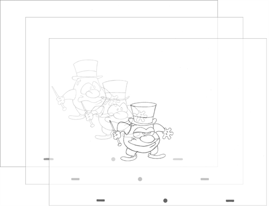
Peg holes in your drawings must be filled with black in the final scanned image for the optical registration to be able to locate them. Your scanner must be modified prior to scanning to ensure black peg holes appear in the scanned image.
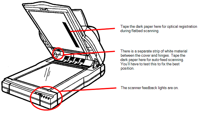
For ADF Scanning
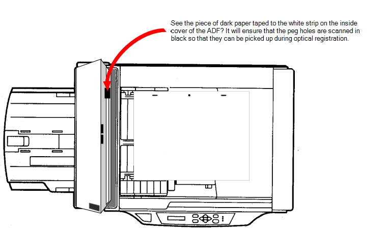
Tape a piece of dark paper to the ADF feeder in the position where the peg holes will pass as they are scanned.
If you don't place the black tape on the ADF paper path, the peg holes in the drawing pass in front of a white background. This does not provide enough contrast for the Scan module to distinguish where the peg holes are and it will not be able to register and align the autofeed drawings.
For Manual Scanning
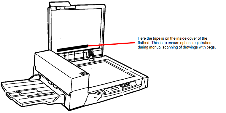
Tape a piece of dark paper to the scanner cover above the position of the peg holes.
RICOH Scanner
Fujitsu Scanner - ADF
Fujitsu Scanner - Cover
Before you perform this procedure, you need the following materials:
| • | A strip of black adhesive tape approximately 1.25 inches (3.5 cm) by 0.75 inches (2 cm). Black plastic electrician's tape is fine. |
| • | A sheet of drawing paper with field size and peg hole locations identical to the type that you intend to scan with the autofeeder. |
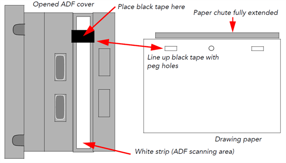
- Turn off the scanner's power and open the ADF cover.
- Place the paper guides in their scanning position. This will depend on your scanner and any modifications you made to it.
- Place the drawing paper in the paper chute with the peg holes toward the back of the scanner.
The top edge of the paper should touch the paper guide closest to the back of the scanner.
- Slide the paper into ADF chute.
- Place the strip of black tape across the width of the white strip on the inside of the ADF cover. Use the peg holes in the drawing paper as a visual guide.
- Close the ADF cover and scan a few test drawings to see that the Scan module can identify the peg holes.
Mounting the Peg Bar and Calibrating the Scanner
Autofed and manually pegged drawings must register against each other if you intend to use both scanning methods. Therefore, you must calibrate the scanner so that it can register the peg holes accurately using the peg bar.
Before you perform this procedure, you will need the following materials:
| • | An ultra-thin peg bar. Suggestion: Audio-Visual Stainless Steel Pegbar (catalog number AP105) |
| • | Accurate ACME standard registration |
| • | 3-peg, single-field length (0.05" x 1.5" x 12.0") (1.27mm x 38 mm x 304.7mm) |
| • | Low brass pegs (1/16" in height) (1.58 mm in height) |
| • | Lightweight sprung stainless steel base |
| • | Ideal for work requiring exposure on a process camera, print down frame or scanning bed |
This is obtainable from Chromacolour International www.chromacolour.com
| • | A drawing with field size and peg hole locations identical to the type you intend to scan. |
Instead of using a drawing of a character or object, you may find it helpful to create a test "drawing" by placing a sheet of drawing paper over a field chart and tracing several heavy line segments from the field chart.
For more accurate calibration, draw lines from the centre to the edges of the paper. This will give more reference points at various locations on the paper. For example, trace over the centre X and several corners of the fields from the centre out towards the edges of the field chart. Then peg and autofeed the test drawing as described in the following procedure.
Before calibrating the scanner:
| ‣ | Create a small scene in Harmony using the test drawing. |
| ‣ | Using Control Center, create a job that has one scene. |
| ‣ | Using Harmony, create an exposure sheet for the job that has two drawing columns (one for the drawing you will autofeed and one for the drawing you will manually peg before scanning). |
- Create a test scene.
- Open the Scan module and open the elements you created.
- Perform an Autofeed scan of the test drawing in the autofeed element, with Optical Registration enabled.
- After the drawing has vectorized, load it in Stage by reopening the scene.
- Loosely tape the peg bar to the scanner bed (centre the bar horizontally on the scanner bed; move the bar vertically on the top of the scanner bed).
- Scan the pegged drawing with the Autofeed feature off.
- After the drawings has vectorized, load it in Harmony by reopening the scene, and comparing its alignment with the drawing scanned in step 4.
- If the two images do not align, move the peg bar and rescan the pegged drawing again.
- Repeat these steps until you have aligned the drawings. When the peg bar is in the desired position, securely attach the peg bar to the scanner bed. Keep the test drawing for future use.