Drawing Layer Properties Reference
The drawing layer's properties is composed of the following tabs:
| • | Transformation Tab |
| • | Drawing Tab |
| • | Controls Tab |
| • | Advanced Tab |
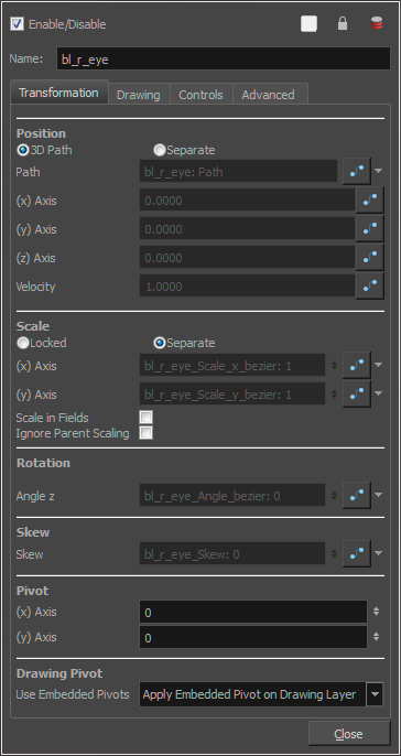
The Transformation tab contains parameters for adjusting the position, scale, rotation, skew and pivots of an element.

| Parameter |
Description |
|||||||||
| Position |
3D Path: Lets you use a 3D path function to animate an element. Separate: Lets you independently edit the different coordinate fields. Path (x) Axis: Lets you type in a new East/West coordinate corresponding to the desired position. Path (y) Axis: Lets you type in a new North/South coordinate corresponding to the desired position. Path (z) Axis: Lets you ype in a new Forward/Backward coordinate corresponding to the desired position. Velocity: When the 3D Path option is selected, lets you set the speed at which |
|||||||||
| Scale |
Locked: Resizes the element while keeping its ratio. The X and Y axes scale proportionally Separate: Resizes the element allowing to modify the ratio (squash and stretch). (x) Axis: Lets you type in the horizontal scale value. (y) Axis: Lets you type in the vertical scale value. Scale in Fields: Instead of using the standard scaling units, when this option is enabled, images are scaled using field units, based on the traditional animation field chart. Ignore Parent Scaling: When this option is enabled, any scaling value applied to a parent layer is ignored in the current layer. This can be handy in cut-out rigs when you need to scale an arm without affecting the forearm. |
|||||||||
| Rotation |
Angle z: Lets you type in a degree value for the rotation angle. Note that you can enter values greater than 360 and -360 degrees. If you enter 720, the object will rotate twice. |
|||||||||
| Skew |
Skew: Lets you type in a degree value between -90 to 90 for the skew angle. |
|||||||||
| Pivot |
(x) Axis: Lets you type in a new East/West coordinate corresponding to the desired position. (y) Axis: Lets you ype in a new North/South coordinate corresponding to the desired position. |
|||||||||
| Drawing Pivot |
Use Embedded Pivots: Harmony has three types of pivots:
To permanently move a peg pivot, use the Rotate or Scale tool. You can also directly type the values in the Layer Properties window in the Pivot section's (x) Axis and (y) Axis fields. In the Layer Properties window, in the Drawing Pivot section, select the Don't Use Embedded Pivot option to use the permanent pivot.
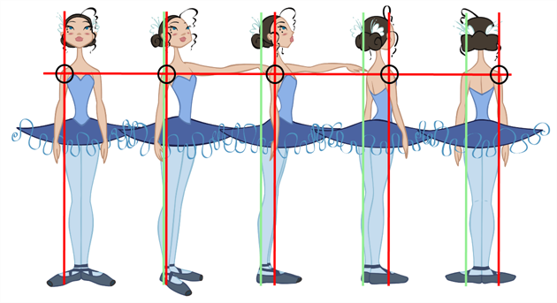
You can set a different pivot for each one of your drawings. For example, if you have a series of drawings from different views, they are not likely to rotate from the same location. In that case, you can set a different pivot for these drawings by using the Drawing Pivot In the Layer Properties window, in the Drawing Pivot section, select the Apply Embedded Pivot on Drawing Layer option to use the drawing pivot directly on the drawing layer. If you want to apply the drawing pivot to a parent peg to force the peg to follow the drawing pivot variations, enable the Apply Embedded Pivot on Parent Peg option.
For a simple character rig, it is recommended to set the Peg pivot (even on drawing layers) using the Rotate |
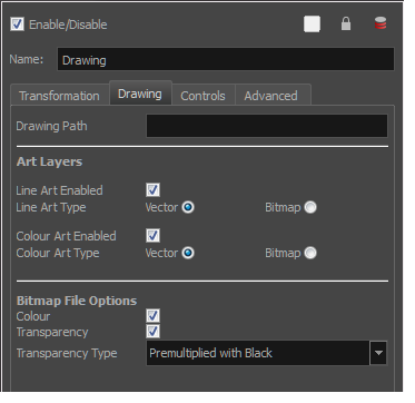
The Drawing tab contains parameters for the element columns, designating art layers, and setting bitmap options.

| Parameter |
Description |
| Art Layers |
Overlay Art Enabled: Enables the Overlay Art display. Line Art Enabled: Enables the Line Art display. Colour Art Enabled: Enables the Colour Art display. Underlay Art Enabled: Enables the Underlay Art display. Overlay Art Type: Allows you to set the Overlay Art as Vector or Bitmap type. Line Art Type: Allows you to set the Line Art as Vector or Bitmap type. Colour Art Type: Allows you to set the Colour Art as Vector or Bitmap type. Underlay Art Type: Allows you to set the Underlay Art as Vector or Bitmap type. |
| Bitmap File Options |
When an image is created with an external software and that image has some transparency, there are several formats the software can use when writing the RBG channels. The purpose of the four import options for the transparency is for the user to tell Harmony how to interpret the RGB channels of the imported image. The correct option has to match the ouput format of the software that was used to create the image in the first place. For instance, if the you used Adobe Photoshop and exported an image as Straight, then it should be imported in Harmony as Straight in order to get the correct result. Note that if the image has no alpha channel or if it does have an alpha channel and all the pixels are 100% opaque, it does not make any difference which option is selected. Colour: Controls the production of colour information from bitmap images. If this module reads 3 or 4-channel bitmaps, this selection determines whether the colour should be read or ignored. If this module reads 1-channel bitmaps, this selection determines whether the channel should be read as colour. When this option is selected with 1-channel images, the resulting image will be a greyscale image. Transparency: Controls the production of alpha information from bitmap images. If this module reads a 1 or 3-channel image, this option will create a matte from the colour values in the image. If the module reads a 4-channel image and this option is not selected, the alpha information in the image will be ignored. |
|
Transparency Type Premultiplied with Black: Semi-transparent pixels in the original image are blended with black. Premultiplied with White: Semi-transparent pixels in the original image are blended with white. Straight: Semi-transparent pixels in the original image are left as is (unmatted). Clamp Colour to Alpha: Semi-transparent pixels in the original image are blended with black. On import, each of the RGB channels is clamped so that a color value never exceed the alpha value for a given pixel. When the RGB values are multiplied with the alpha value, that is to say, if you have a pixel of value R=247, G=188, B=29 and the alpha is 50% or the image has a 50% transparency, then the actual RGB values output would be half of the amounts listed above. |
The Controls tab contains animation control options.
| Parameter |
Description |
| Animation |
Animate Using Animation Tools: By default, a drawing layer can be animated using the same parameters as a peg, but you can disable this feature. Being able to switch your drawing layers so they can no longer be animated without a peg has certain advantages. In cut-out animation, it is easier to separate your drawing exposure and keyframes to change timing easier and rearrange keyframe position in the Timeline view. This feature is also available for backward compatibility when bringing in templates created in older versions of the software, so as not to lose their offset keyframes or drawing substitution keyframes. |
| Spline Offset |
In the X, Y and Z axis fields, type the coordinates of where you want to offset the visual trajectory. By default, the trajectory is displayed at the centre drawing, using the layer's pivot position. If you want to move it so it corresponds better with your drawing, either type new coordinates or use the Spline Offset tool available in the Advanced Animation toolbar. To display the trajectory in the Camera view, select your drawing and select View > Show > Control. You can also press Shift + F11 (Windows/Linux) or ⌘ + F11 (Mac OS X). |
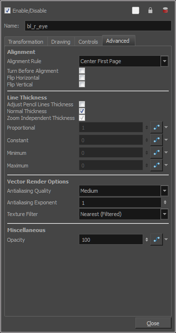
The Advanced tab contains options for setting the alignment of drawings, line thickness, vector render options, and more.

| Parameter | Description | |||||||||||||||||||||||||||||||||
| Alignment |
Alignment Rule: The alignment rule selections are intended to deal with drawings that were created on paper of a different size or orientation from the default alignment rule (set up in the Scene Settings dialog box) or imported bitmap images. The drawings are then scaled to match the Harmony alignment rectangle. Note that alignment rules are not based on the camera frame, but on the scene frame. Refer to the Fundamentals Guide to learn more about scene alignment and scene settings.
|
|||||||||||||||||||||||||||||||||
|
Turn Before Alignment: Rotates the drawings in the selected element 90 degrees to the left before scaling and aligning them according to the alignment rule, and before performing any offset, rotation or scaling for the element or peg. This and the Alignment Rule are intended for drawings that were created on paper of a different size or orientation than the other paper in the scene, and requires alignment so they are treated accurately. |
||||||||||||||||||||||||||||||||||
|
Flip Horizontal: Flips the drawing on the X-axis. |
||||||||||||||||||||||||||||||||||
|
Flip Vertical: Flips the drawing on the Y-axis. |
||||||||||||||||||||||||||||||||||
| Line Thickness |
As you move the camera in your scene along the Z-axis, notice that, logically, the lines of the elements become thicker the closer the camera gets to the drawing. If you prefer the lines to remain the same size or become thicker at a different speed, you can use the thickness feature to adjust your brush stroke and pencil line thickness. You can modify the size of the lines even if the camera is not animated. To learn how to use this feature, see Camera Truck-ins and Line Thickness. Adjust Pencil Lines Thickness: Lets you work with pencil lines and adjust their thickness. You will not see any changes to lines in the Camera view OpenGL mode. You must switch to the Render mode. Normal Thickness: Disables all overrides on the brush stroke line thickness. This option must be enabled in order for the pencil line thickness parameter and pencil lines to appear. If you want to modify the brush stroke thickness, deselect this option. To enable brush strokes to work with the line thickness feature, you must first create central strokes in the Colour Art layer. The central strokes control the line variation of your brush strokes in the Line Art layer. Select Drawing > Create Colour Art from Line Art. Zoom Independent Thickness: Select this if you want your line thickness to remain constant independently from the camera move. Everything else will increase in size, but the line thickness will stay the same. Proportional: Enter a multiple by which you want to increase the line thickness base on its original thickness. A value of 1 will result in no change; a value of 0 (zero) will hide the lines. Constant:Enter a value in pixels (based on a 720x540 screen resolution) to indicate the amount of pixels you want to add around the existing line. Minimum: Enter a value in pixels (based on a 720x540 screen resolution) for the minimum line thickness allowed. Maximum: Enter a value in pixels (based on a 720x540 screen resolution) for the maximum line thickness allowed. |
|||||||||||||||||||||||||||||||||
| Vector Render Options |
Higher quality images require more time to render and more system memory. Choose a lower quality if you are rendering a pencil test.
|
|||||||||||||||||||||||||||||||||
| Miscellaneous |
|

