


Toon Boom Harmony 11 Release Notes
Version 11
Here are the new features and improvements in Toon Boom Harmony 11:
| • | Timeline and Animation Improvements |
| • | Network |
| • | Modules and Effects |
| • | Library - Importing Files through the Library |
| • | Drawing and Camera View |
| • | Import |
| • | Colour View |
| • | Game Export |
| • | Harmony Cloud |
| • | Toon Boom Harmony 11 Release Notes |
| • | Toon Boom Harmony 11 Release Notes |
| • | Sketch Module |
| • | Draw Module |
| • | Miscellaneous changes |
Timeline and Animation Improvements
In this version of Harmony, the Timeline view has been improved to make it clearer and more predictable.
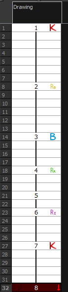
Marked Drawings in the Timeline
When you add markers to a project, such as K for Key Drawing or B for Breakdown, they are now visible in the Timeline. The colours of the Key Drawing frame and Breakdown markers are customizable via the same Marked Drawing preference settings.
| 1. | In the Xsheet view or Timeline view, select the cell that you want to mark. |
| 2. | Do one of the following: |
| ‣ | In the Mark Drawing toolbar, select an icon. |
| ‣ | In the Xsheet view or Timeline view menu, select a command in Drawing > Mark Drawing. |
| ‣ | Right-click the selection and select Drawings > Exposure > Mark Drawing. |

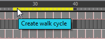
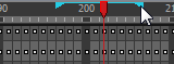
Scene Markers
Scene markers are used to display visual indicators at the top of the Timeline in the frame counter area. Use it to denote anything relevant to your work. You can indicate at what frames you want to clean up work, a change in action, or where you intend to apply an effect. You can also add a note to a scene marker, which is displayed as a tooltip when you hover over the scene marker.
| 1. | In the Timeline view frame counter, select a range of frames on which to mark your scene. |
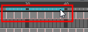
| 2. | Right-click and select Scene Markers. |
The Timeline Scene Marker dialog box opens.
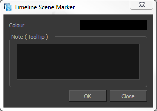
| 3. | Click in the Colour box to select a colour for your scene marker. |
| 4. | In the Note field, enter text to display as a tooltip. |
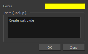
| 5. | Click OK. |
In the Timeline view, the scene marker is displayed over the selected frame counters. Hover over the scene marker to view its note which displays as a tooltip.
Custom Timeline Colours
The ability to change the colour of a Timeline layer has been improved. Two things have been done. For an element, it’s not only the cell blocks that will reflect the custom layer colour, but also the background of that layer. Also, you now have the ability to change the colour for almost all element types via the Timeline (like pegs).
Key Exposures
If you want to make sure that a certain drawing remains exposed on a certain frame and is not overwritten by a drawing swap done on an earlier frame, you can use the key exposure function. The key exposure feature breaks a drawing block into two pieces. The same drawing is used in both blocks. If you modify the artwork in one, the artwork will also be modified in the second one. But if you swap the exposure of the first one for another drawing, the second block will remain with the first drawing. This feature is used to avoid messing up your animation key poses. It is most frequently used on the mouth layer.

| 1. | In the Timeline view, select the drawing cell you want to set as your key exposure. |
| 2. | In the Timeline View toolbar, you can click on the Add Key Exposure |
| ‣ | To delete a key exposure, click on the Remove Key Exposure |
Copy/Paste
There is no more auto filling before pasted frame(s). There are held frames and key exposures. A held frame is just a frame that has no specific value but just follows the preceding key exposure’s value. When you paste Key Exposures, Blank, or Held frames it will try to stay the same as the source. A special case is when pasting a Held frame on a different drawing; then it will create a Key Exposure of the source held.
When you paste on different drawings:
| • | The value (Held, Blank or Key Exposure) is extended. |
| • | A Held becomes a key exposure. |
| • | A blank stays a blank. |
| • | A key exposure stays a key exposure. |
When pasting on the same drawing, we do the same as above:
Same behaviour in Xsheet for the copy/paste.
Sliding Behaviour for Drag and Drop in Timeline and Xsheet
There have been improvements to how dragging and dropping an exposure/keyframe works. This has been implemented to avoid unpredictability in the way certain elements were being extended automatically when performing some of these types of operations:
| • | Cut, copy, paste |
| • | Drag and drop or sliding |
| • | Auto-extend |
When the source and destination are on the same drawing or blank, there is an extension in that the Held frame is kept:
| • | No new Key Exposure is created when you slide a held exposure or a blank exposure. |
| • | No new Key Exposure is created after the Key Exposure is slid over but the original is kept. |
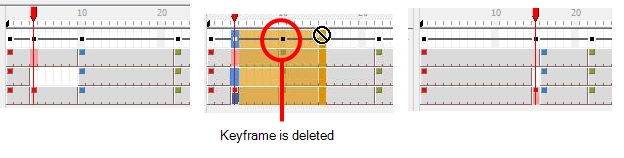
When the destination is a different image, there is no extension:
| • | The held, blank, or key exposures are moved and a key exposure of the different drawing is created after. |
| • | Some keyframes or exposures located between the source and destination might be replaced or deleted. |
There is a similar behaviour in the Xsheet. When you use the left side of the cells in the Xsheet, it does the same as the slide in the Timeline view for the drawing and function columns. The Annotation and Sound columns work like before; a slide will not be performed, but cut and paste of the selected area.
You can see the override area in preview like in the Timeline view.
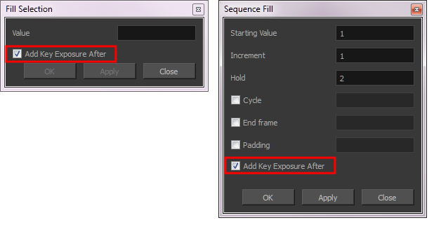
Filling Selections in the Timeline View
When filling a selection or sequence or filling a selection randomly, the Add Key Exposure After option allows you to insert a keyframe in the frame following the last cell in a selection. This option appears in these dialog boxes: Fill Selection, Sequence Fill, and Fill Cells Randomly.
No Auto-fill on Preceding Drawings
In previous versions of Harmony, when creating a new drawing that is placed after a series of blank cells, the previous drawing's exposure filled the empty cells up to the new drawing. In Harmony 11, this no longer happens. The exposure of the previous drawing does not fill the blank cells preceding the new drawing.

Drawing Substitution Will Not Auto-fill Preceding or Following Frame(s)
You can swap images in the Timeline or Library view. When you use the Drawing Substitution area in the Library view, you are not selecting drawings from the Library; you are selecting drawings contained in your scene layers.
It is important to understand that when a drawing is swapped, its entire exposure is replaced up to the next drawing block.

Although, if you select a frame range to be swapped, the following exposure will remain the same even if it was part of the same drawing block.
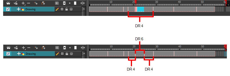
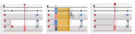
Fill Empty Cells
After you have created several single frame drawings, you can extend their exposure to fill the empty cells between them.
Before

After

Merging Artwork
You now have the ability to Merge layers or drawings. The feature is mostly accessible via the Timeline, but some of it can be accessed from the Xsheet.
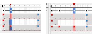
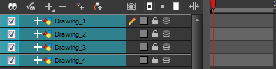
Merging Selected Layers
You can merge two (or more) selected layers. This operation merges the drawing elements from the top all the way down to the last selected layer (horizontally). The action of merging will copy drawing elements from other selected elements and merge them into the bottom layer. The original layers will be deleted.
| 1. | On the left side of the Timeline view, select multiple layers. |
| 2. | In the Timeline view menu, select Layers > Merge Selected Layers. |
| 3. | Merge Layers with or without conversion to the destination art-layer type (bitmap or vector). |
The top layers are merged down into the bottom one and the top layers are deleted.
There is no warning message, but the action can be undone.
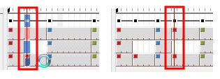
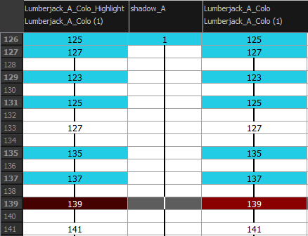
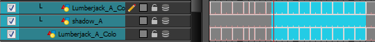
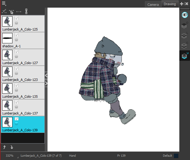
Merging Selected Drawings
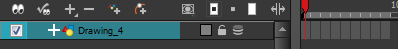
You can merge drawings by selecting the drawings on the right side of the Timeline view. This will not delete any drawing layers. Instead, the artwork is copied into the destination layer. Only the exposure on the source is deleted, not the drawings themselves. The artwork for the original can always be recovered, but the timing cannot.
| 1. | Select some drawings from the right side of Timeline view. |
| 2. | Do one of the following: |
| ‣ | Right-click the selection and select Drawings > Merge Selected Drawings. |
| ‣ | From the Timeline view menu, select Drawings > Merge Selected Drawings. |
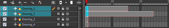
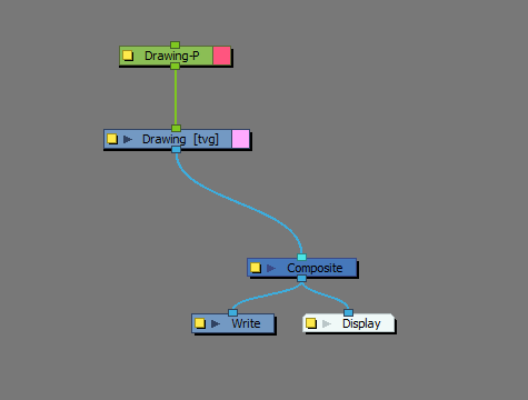
The drawing elements are copied down into the last selected element, and the exposure is removed from the original.
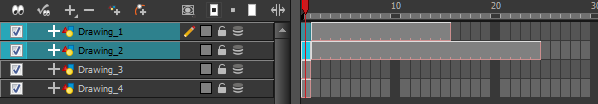
In this example, the drawing merged from Drawing_1 remains accessible via the Drawing Substitution area in the Library view, but is no longer exposed in the Timeline view.
Cloning Columns
Cloning a column provides you with a copy of the selected element that uses the same drawings as the original. For example, if you modify a drawing in the cloned or original column, it is updated in both columns.
In Harmony 11, you can choose whether or not to copy the column exposure to the cloned column.
| • | Clone Selected Layers (Drawings Only): You can modify the column exposure independently from each other and the drawings remain linked. |
| • | Clone Selected Columns (Drawings and Timing): You can copy the column exposure and the drawings and timings remain linked. |
| 1. | In the Xsheet view, select the column you want to clone. |
| 2. | Do one of the following: |
The new cloned column appears.
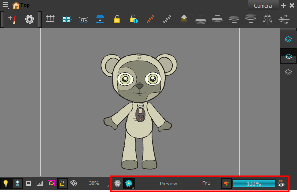
Art Layer Toolbar
Until now, control of the active art layer has always been in the status bar at the bottom of the Camera and Drawing views. These controls have been moved to a toolbar in the Camera and Drawing views.
Rendering Toolbar
The Rendering toolbar has been moved to the Camera status bar. Many of the display modes are now buttons.
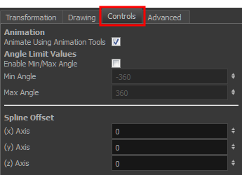
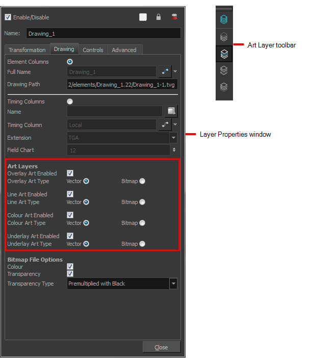
New Tab in Layer Properties Window
There is a new tab in the Layer Properties window called Controls, which contains new options for the bitmap art layers. Some properties were also moved to the other tabs in this window.
Drawing with Bitmap Brushes

With Harmony, you now have the choice to draw with vector or bitmap brushes. When adding a new layer, you can set your layers (Line Art, Colour Art) to be vector or bitmap. This way, you can draw in bitmap and paint in vector, draw everything in bitmap, or whatever other combination suits you.
When adding a new drawing layer to the Timeline view, you can select the art mode for each art layer. You can set the Line Art layer to be vector, while setting the Colour Art as bitmap. You also have the opportunity to readjust those later by converting them from one to the other. If you are using the Overlay and Underlay layers, you can also set those to either bitmap or vector.
If you selected the incorrect art mode for your layers, you can open the Layer Properties view and modify them there directly. If you switch the art mode for a layer that already has strokes on it, the artwork will NOT be converted. You will be able to add new strokes. A drawing with bitmap strokes will be converted to a vector layer but the bitmap artwork will remain as bitmap. You will be able to use vector drawing tools to continue drawing on it. A drawing with vector lines switched to a bitmap layer will allow you to draw new bitmap strokes and move the vector strokes with the Select tool, but you will not be able to edit the vector art further. You need to convert the drawings in order to pass the artwork from one mode to the other.
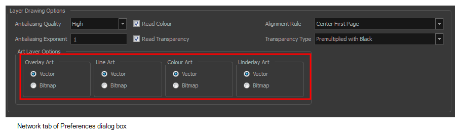
To always reuse the same art mode settings, you can adjust them in the Preferences dialog box.
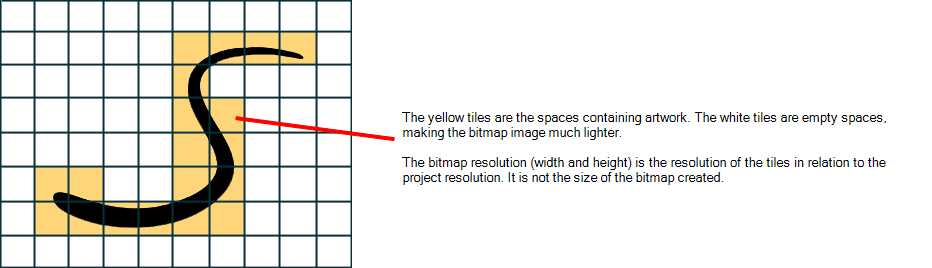
Before you start drawing in bitmap, it is important to understand that your artwork will now be resolution dependent. If you zoom in your scene, you artwork will be enlarged. It is important to plan ahead of time and decide how high of a resolution you need your artwork to be. If you plan to zoom in your scene, the smallest section of the image that the camera will frame must be 100% the size of your scene resolution. For example, if your scene is 1920 x 1080, the smallest portion of your bitmap image has to be 1920 x 1080. It is important to change the bitmap layer resolution before you start drawing.

The bitmap resolution can be set at the scene level or drawing level. The setting at the scene level affects newly created bitmap art layers.
There is a function to change the default resolution of bitmap art for individual drawings. It is useful if you want to change the quality of bitmap art you did. For example, you used the default scene’s resolution for bitmap art but then discover you are zooming quite close into the lines. If you do not want to see the pixels appear too much when you are zoomed in, you can put 200% and the bitmap art will have a higher quality with smaller pixels. You can use this function on multiple drawings using the Apply to All Drawings option. Changing this option will affect existing and selected bitmap art layers.
If you drew an outline drawing on a bitmap layer, you can vectorize your artwork. Using a vector drawing layer, you can simply select your bitmap drawing and the vector cell on which you want your new vector layer to be, and use the Vectorize Line Art in Selected Drawing function.
Not all drawing tools are available when working on a bitmap layer. You can use the following tools:
| • | Select tool |
| • | Cutter tool |
| • | Reposition All Drawings tool |
| • | Brush tool |
| • | Eraser tool |
| • | Text tool |
| • | Paint tool |
| • | Paint Unpainted tool |
| • | Repaint tool |
| • | Unpaint tool |
| • | Dropper tool |
| • | Pivot tool |
| 1. | In the Timeline view, click the Add Drawing Layer |

The Add Drawing Layer dialog box opens.

If you are using Overlay and Underlay layers, they are also displayed.

| 2. | For each art layer, select the Vector or Bitmap option. |

| 3. | Click OK. |
| 1. | Open the Layer Properties view. |
| 2. | In the Timeline view, select the layer you want to edit. |
| 3. | In the Layer Properties view, select the Drawing tab. |

| 4. | In the Art Layers section, select the art mode for each art layer. |
| 1. | From the top menu, select Edit > Preferences ( Windows/Linux ) or Stage Paint > Preferences ( Mac OS X ). |
| 2. | In the Network tab, go to the Layer Drawing Options section. |

| 3. | Set the art layers to the desired art mode. |
| 4. | Click OK. |
| 1. | In the Timeline view, select the layer you want to convert the drawings for. |
| 2. | From the Timeline View menu, select Layers > Convert Drawings to Match Art Layer Type. |
| ‣ | You can also right-click on the selected layer and select Convert Drawings to Match Art Layer Type. |
All drawings in the layer are converted to the selected art mode. Note that bitmap strokes are not vectorized when converted to a vector art layer. They are simply inserted in a square vector frame containing a bitmap texture.
| 1. | From the top menu, select Scene > Scene Settings. |
The Scene Settings dialog box opens.
| 2. | In the Bitmap Resolution tab, change the bitmap resolution settings. |
| 3. | Click OK. |
The bitmap resolution settings at the scene level affects newly created bitmap art layers.

| 1. | In the Timeline view, select the drawing whose resolution you want to change. |

| 2. | From the top menu, select Drawing > Change Bitmap Drawing Resolution. |
The Change Bitmap Drawing Resolution window opens.

| ‣ | Resample Bitmap: When this option is enabled, the existing bitmap image is modified to match the new resolution. If the width and height are increased, more pixels will be created to enlarge the image. Visually, the existing artwork will look the same, maybe a little bit smoothed out, but the size will look the same. When this option is disabled, the artwork is not modified. Only the reference grid is resized. If the scene resolution is 1920 x 1080 and you reduce the bitmap resolution to 960 x 540, the image will be scaled down to half the size of the scene. |
| ‣ | Apply to All Drawings: When this option is enabled, the settings modification will be applied to all drawings in the layer. |
| 3. | Change the bitmap resolution. |
| 4. | Click OK. |
| 1. | In the Timeline view, add a bitmap drawing layer. |
| 2. | In the Tools toolbar, select the Brush |
| 3. | In the Colour view, select a colour. |

| ‣ | To toggle the bitmap colour picker from HSV to RGB, in the Colour View menu, select Colour > Bitmap Colour Sliders > HSV Sliders or RGB Sliders. You can also right-click directly on the colour sliders and select the option of your choice. |

When using bitmap colours, there is no longer a link between the painted zones and selected colour. You can modify the colour picker as much as you want. Your drawing will not be affected. You can still select colours from your vector colour palette to use the same tint, but you will not create links between your drawing and the swatches.
| 4. | In the Camera or Drawing view, start drawing. |

| 1. | In the Timeline view, add a vector drawing layer BELOW the bitmap drawing layer containing the drawing to vectorize. In your bitmap drawing, the artwork to vectorize must be placed on the Line Art layer (default drawing layer). |

| ‣ | If you place your vector drawing on top of the bitmap layer, you will not be able to perform the operation and a warning dialog box will open. |

| 2. | In the right side of the Timeline view, select the bitmap drawing and the corresponding cell in the vector drawing layer. |

| 3. | Right-click on your selection and select Drawing > Vectorize Line Art in Selected Drawing. |
The Convert to Vector Drawing dialog box opens.

| 4. | In the Vectorization section, select the vectorization preset of your choice. You can customize your own preset using the Add or Edit buttons. |
| 5. | Click OK. |
Your vectorized drawing is created in the vector drawing layer. Your bitmap drawing remains intact.
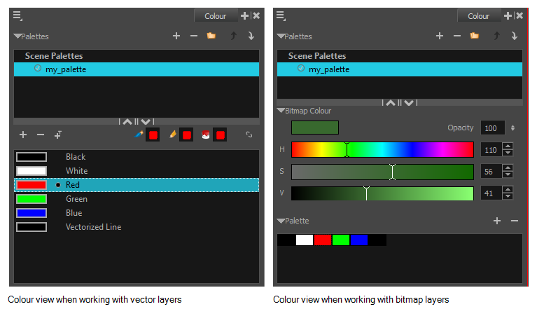
Bitmap Colour View
When working with bitmap layers, the Colour view is slightly different than the one you see when working with vector layers. When editing colours, you will use the HSV/RGB controls.
When using bitmap colours, there is no longer a link between the painted zones and selected colour. You can modify the colour picker as much as you want. Your drawing will not be affected. You can still select colours from your vector colour palette to use the same tint, but you will not create links between your drawing and the swatches.
Using Independent Colours when Working with Bitmap Layers
When working in the Colour view, by default the current colour is active for both vector and bitmap layers. You can however, use different reference colours for each layer.
When using bitmap colours, there is no longer a link between the painted zones and selected colour. You can modify the colour picker as much as you want. Your drawing will not be affected. You can still select colours from your vector colour palette to use the same tint, but you will not create links between your drawing and the swatches.
| ‣ | From the Colour view menu, select Colours > Independent Bitmap Colour. |
Whichever colour you choose as the reference color is retained for that layer type.
Overlay and Underlay Art Layers
All art layers have always been available to you by default. There is a new option (on by default) that limits the art layers to Line Art and Colour Art only. If you want to also have the overlay and underlay art layers available, you must turn on this preference which located in the Advanced Options section of the Advanced tab of the Preferences dialog box.
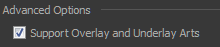
This preference controls access to the overlay and underlay art layers in the Preferences dialog box, the Layer Properties window, and in the Art Layer toolbar.
Network
Custom Layer Colours
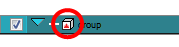
When you change the colour of elements displayed in the Timeline, it will be reflected in the module(s) in the Network view. The corresponding colour is displayed on the right side of the module.
Show All Modules
When your scene contains many modules and you cannot see them all, you can display all modules at that level.
| ‣ | From the Network View menu, select View > Show All Modules or press Shift + comma (,). |
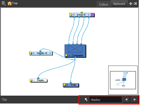
Searching in the Network View
At the bottom-right of the Network view is a new search field that lets you find modules. This search is not case-sensitive. When your module is found, it is selected and centred in the view. You can press the Previous and Next buttons to go through a multiple selection, with each node displayed in turn.
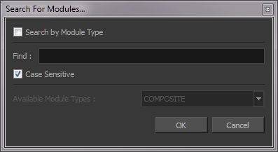
Searching by Name, Pattern or Module Type
You can search through the Network view and select all modules that match a certain criteria, either by module name (case sensitive or not) or by module type. There only a few operations that can be done on a group of selected modules, such as delete or disable/enable.
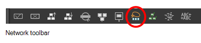
To access the Search For Modules features, display the Network toolbar and then click the Search For Modules ![]() icon.
icon.
Setting Properties for Many Layers
When dealing with several modules, you may frequently want to modify a series of settings. Instead of opening each individual Layer Properties editors, you can use the Set Properties for Many Layers function to change common settings in one single click.
This function allows you to modify the state of the following settings:
| • | 3D path or Separate mode |
| • | Use Embedded Pivot |
| • | Overlay |
| • | Line Art |
| • | Colour Art |
| • | Underlay |
| • | Animate Using Animation Tools |
You can access this function in the Network View toolbar. You can also add the button to your Timeline View toolbar through the Toolbar Manager.
| 1. | In the Network view, select all the layers you want to modify at the same time. |

| 2. | In the Network View toolbar, click on the Set Properties for Many Layers button. |
The Set Properties for Many Layers dialog box opens.

| 3. | Modify the properties. |
| ‣ | If your modules have different parameters enabled for a certain setting, leave the As Is option selected to avoid modifying it. Each module will keep its original setting. |
| ‣ | Select any other options for all modules to change to this parameter regardless of their original setting. |
| 4. | Click OK. |
Publish Attribute Mode
To quickly access parameters for modules that are grouped, you can use the Publish Attribute Mode feature to select your most common parameters to modify and make them appear in the group Layer Properties editor. This way, you can access them directly without having to enter the group every time.
| 1. | In the Network View menu, select View > Publish Attribute Mode. |
| 2. | In the Network view, enter the group containing the modules you want to promote. |
| 3. | Select the module that contains the attributes you want to publish. |
| 4. | In the Layer Properties view, select or deselect the publishing options for the different parameters. You can easily distinguish them as they are labeled in red. |

| 5. | Repeat the previous step for all the modules that have attributes you want to publish. |
| 6. | In the Network view, exit the group. |
| 7. | Select the Group module. |
In the Layer Properties view, you can see all published attributes. The different modules are tabbed for easy access and organization.

Groups with certain published attributes are displayed differently in the Timeline view. When you expand a group, only published attributes are display.
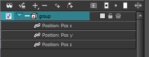
At times, you may not want the Timeline view to display only the published attributes. If you want to turn this off just for the Timeline, press [Ctrl] and click the plus (+)/minus (-) sign to the left of the group icon. The triangle beside the group icon turns red to indicate that you are in Publish Attributes mode.
Modules and Effects
Mesh Warp
The Mesh Warp effect lets you distort your drawings. Using this module, you can create effects such as a character in a warped mirror or looking through a glass jar. You can also animate the position of the grid to perform the distortion over time.
The main difference between the Envelope tool and the Mesh Warp is that the Mesh Warp can be animated over time with keyframes, whereas the Envelope tool cannot.
The Mesh Warp module is a position module, same as a Peg module.


| 1. | In the Module Library, under the Filter tab, select the Mesh Warp module and drag it to the Network view. |
| 2. | In the Network view, connect the Mesh-Warp module to your drawing or group modules to deform. |
| 3. | In the Network view, select the Mesh Warp module. |
| 4. | From the top menu, select View > Show > Control or press Shift + F11 (Windows/Linux) or ⌘ + F11 (Mac OS X) to display the deformation grid in the Camera view. |

| 5. | Move the intersection points and move the Bezier handles to deform the grid. |

| 6. | Grab the grid in the void spaces to pan it around. Using keyframes, you can animate its position over time. |
Use the Mesh Warp editor to adjust the grid size, deformation quality and the region of interest.

| Parameter | Description |
| Rows | Increase or decrease the Rows value to change the amount of rows to use in the deformation grid. |
| Columns | Increase or decrease the Columns value to change the amount of columns to use in the deformation grid. |
| Region of Interest | Select the 2D Path option if you want both your X and Y curves to be controlled by the same velocity function. Select the Separate option if you want your X and Y curves to be independent and have independent velocity. |
| (x) Axis | This is the X position of the gird. This value can be animated overtime to move the grid horizontally. |
| (y) Axis | This is the Y position of the gird. This value can be animated overtime to move the grid vertically. |
| Width | This is the width value of the gird. This value can be animated overtime to squash or stretch the grid horizontally. |
| Height | This is the height value of the gird. This value can be animated overtime to squash or stretch the grid vertically. |
| Deformation Quality | This is the quality of the warm deformation. It ranges from Low to Extreme. The higher the quality, the better the formation will look, but the longer it will take to render. |
Flatten Module
The Flatten module is used to transform 3D objects into flat planes when ordered in the Composite module. That plane can then be moved around like any other drawing. Instead of intersecting with 2D layers, the 3D object will either be behind or in front.
When all objects are at the same distance (Z value) from the camera, the order is based on the Composite ports. When elements are placed at different distances from the camera, the Z axis value overrides the composite port ordering.


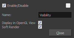
Visibility Module
The Visibility module controls whether an item is visible in OpenGL mode versus the software Render mode in the Camera view. If soft render is not enabled, the layer will not be exported.
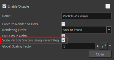
Visualizer Module
There is a new option in the Visualizer module that respects the scaling of a particle system so you can position and resize it as you like. Old scenes with particle systems will still work as this option is disabled.
Library - Importing Files through the Library
Harmony allows you to import sound files and images directly through the library without going through the Import Files feature. You simply need to open the folder containing your files in the Library view and drag them directly from there.
| 1. | In the Library View menu, select Folders > Open Library. |
| 2. | Browse for the folder containing the files you want to import. |
| 3. | Click Open. |
| 4. | From the Library's template list, drag the file you want to import in the Timeline or Camera view. |

Drawing and Camera View
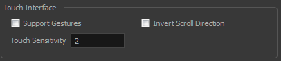
Touch Gesture Support
Touch gesture is now supported in the Drawing and Camera views in Harmony, letting you zoom in and rotate the view. You can set preferences for this feature on the General tab in the Preferences dialog box.
Shift and Trace
The Shift and Trace interface has been improved. Buttons are greyed out unless the proper option is selected, such as when the onion skin is active. You can move the drawings up or down with new buttons at the bottom of the window. There is a more compact arrangement of the buttons.
| 1. | Do one of the following: |
| ‣ | In the Xsheet or Timeline view, select a consecutive cell range from one or several layers. |
| ‣ | In the Xsheet view, hold down Ctrl (Windows/Linux) or ⌘ (Mac OS X), and click on any cell to add it to the selection, even if it is not consecutive. |
| 2. | Do one of the following: |
| ‣ | In the Timeline or Xsheet view menu, select Drawings > Send Drawings to Desk . |
| ‣ | In the Xsheet view, right-click and select Send Drawings to Desk . |
| ‣ | In the Xsheet view, hold down the Alt key and click on the selection. |
The drawing desk opens on the side of the Drawing view.
| 3. | If the drawing desk side panel is hidden, click on the Arrow button, located on the right side of the view. |

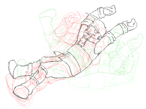
Onion Skinning by Drawing in the Camera View
There has always been a difference between how the onion skinning is displayed in the Camera view vs. the Drawing view. In the Camera view, it is based on the number of frames, and not the actual number of drawings, whereas in the Drawing view, it’s based on the actual number of drawings. In Line test, there is only a Camera view, so the need arose to be able to see the onion skin in that view like you would have seen it in the Drawing view.
Now there is an option to change the onion skins per drawing. When this option is on, two things happen:
You will lose the little blue handles in the Timeline that indicate to what frame the onion skin is being displayed, as it’s no longer per frame, but per drawing
Now the amount of frames a drawing is held for is not relevant, the next and previous drawings refers to exactly that, the drawings on not the frames
| 1. | Do one of the following: |
| ‣ | From the top menu, select View > Onion Skin > Onion Skinning by Drawing. |
| ‣ | In the Camera view menu, select View > Onion Skin > Onion Skinning by Drawing. |
| ‣ | In the Timeline view menu, select Onion Skin > Onion Skinning by Drawing. |
| 2. | Click an icon, menu operation or keyboard shortcut to edit the display. |
| View > Onion Skin Menu Command | Tools toolbar icon | Keyboard Shortcut |
| No Previous Drawing |
|
~ |
| Previous Drawing |
|
! |
| Previous Two Drawings |
|
@ |
| Previous Three Drawings |
|
# |
| No Next Drawing |
|
Ctrl + ` (Windows/Linux) or ⌘ + ` (Mac OS X) |
| Next Drawing |
|
Ctrl + 1 (Windows/Linux) or ⌘ + 1 (Mac OS X) |
| Next Two Drawings |
|
Ctrl + 2 (Windows/Linux) or ⌘ + 2 (Mac OS X) |
| Next Three Drawings |
|
Ctrl + 3 (Windows/Linux) or ⌘ + 3 (Mac OS X) |
| 3. | In the Camera view, the previous and next drawings appear with the current one. |
| 1. | If they are not visible, display the blue onion skin markers in the Timeline view by doing one of the following: |
| ‣ | From the top menu, deselect View > Onion Skin > Onion Skinning by Drawing. |
| ‣ | In the Camera view menu, deselect View > Onion Skin > Onion Skinning by Drawing. |
| ‣ | In the Timeline view menu, deselect Onion Skin > Onion Skinning by Drawing. |
| 2. | In the Timeline view, drag the blue onion skin markers to select the number of previous and next drawings to display. |
| 3. | In the Camera view, the previous and next drawings appear with the current one. |
| 1. | In the Camera or Drawing View toolbar, click the Top Light |
The Top Light dialog box opens.
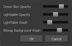
| 2. | Adjust the Onion Skin Opacity slider to modify the opacity value of the onion skin display. |
| 3. | Click OK. |
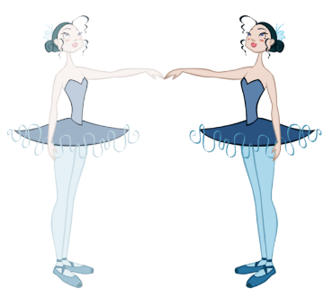
Warping a Drawing Using the Envelope Tool

The Envelope tool lets you deform and warp a drawing selection using a grid envelope and Bezier handles.
| 1. | In the Tools toolbar, select the Envelope |
| 2. | In the Timeline view, select a drawing to deform. |
| 3. | In the Camera or Drawing view, select the region you want to deform |

| 4. | Click and drag the different anchor points to deform the image. |

| 5. | To display more controls, in the Tool Properties view, click on the Show Advanced Controls |

| 6. | You can also increase the width and height of the grid to get more control points to deform your image. |

Envelope Tool Options
Selecting the Envelope tool displays its properties and options in the Tool Properties view.

Increase the width and height values to add more columns and rows to the deformation grids.
Choose between the Lasso ![]() and Marquee
and Marquee ![]() options to change the selection style of the tool.
options to change the selection style of the tool.
| • | Click and hold Alt to temporarily switch from the current mode to the other. |
| • | The Snap to Contour |
| • | The Snap and Align |
| • | The Snap to Grid |
To display more controls, you can click the Show Advanced Controls ![]() button.
button.

The Apply to Line and Colour Art ![]() option uses the concept of Line Art and Colour Art layers. Use this option to apply an action such as selecting or resizing a drawing on both Line Art and Colour Art layers, as well as the Overlay and Underlay layers.
option uses the concept of Line Art and Colour Art layers. Use this option to apply an action such as selecting or resizing a drawing on both Line Art and Colour Art layers, as well as the Overlay and Underlay layers.
The Flip Horizontal ![]() and Flip Vertical
and Flip Vertical ![]() operations flip the current selection horizontally or vertically.
operations flip the current selection horizontally or vertically.
| ‣ | From the top menu, select |

The Rotate 90 Degrees CW ![]() and Rotate 90 Degrees CCW
and Rotate 90 Degrees CCW ![]() operations rotate the current selection 90 degrees clockwise or counter-clockwise.
operations rotate the current selection 90 degrees clockwise or counter-clockwise.
| ‣ | From the top menu, select |
| ‣ | Press Ctrl + 7 and Ctrl + 9 (Windows/Linux) or ⌘ + 7 and ⌘ + 9 (Mac OS X). |
You can modify the central line smoothness of your line using this option. This parameter smooths the deformed lines. Increasing the value will result in a smoother line with fewer control points. The more you increase the value, the less details and curves you will get. Use the left and right arrows to increment the value by one full unit. Use the Up - Down slider to quickly increment the value.
Select Works on Single Drawing
The Select works on Single Drawing option can now be found in the Select tool’s properties as well the preferences. When you change the state in the properties, it will change the Preference so you don’t have to do it every time you start a new session. However changing the preference itself will not change the state in the properties view. It will only take effect the next time you open a session.
Tool Preset Toolbar
The Tool Preset view is now a toolbar. Also, the presets now work in either bitmap or vector mode, depending on the tool. For example, the Brush has a bitmap and vector mode, depending on which art type is selected. If you create a preset while using a bitmap brush, you won’t be able to use that preset when you have a vector art layer selected and vice versa. The unavailable toolbar presets will be greyed out when they are not available.

Playback, Rendering and Export
Camera Clipping Planes
You can change the near and far clipping planes of the camera. The near plane is the point on the camera cone where the camera is and the far clipping plane is the far end of the camera cone. Nothing outside that range is visible. This feature is useful when dealing with 3D elements and 3D sets. For example, the camera can be looking inside a 3D box or room and you might want the foreground wall not obstruct the view of the interior. By default, the near clipping plane is set to 1 field and the far clipping plane is set to 1000 fields.

| 1. | In the Timeline or Network view, select the Camera module. |
| 2. | In the Layer Properties view, go to the Clipping Planes section. |

| 3. | Modify the values of the Near Plane and Far Plane to pull or push the clipping area closer to the camera. Anything behind this plane will no longer be visible. |
Orthographic Camera

The orthographic camera is very specific to the gaming pipeline. It changes the camera type from Perspective to Orthographic. It becomes a camera without vanishing points. This means that there is no more perspective in the Camera view. Objects, when moved on the z-axis, will not change in size or scale.

The orthographic camera can be set via the Scene Settings panel. In order to create scenes with the orthographic camera by default, you need to create a new custom scene resolution. Refer to the Fundamentals Guide to learn about custom resolutions.
| 1. | Select Scene > Scene Settings. |
| 2. | In the Projection section under the Resolution tab, select Orthographic. |

OpenGl Frame Grabber/Improved OpenGL Playback
Playback in OpenGL views has been improved; it also provides a way to capture the frames into memory but interactively in the Camera view during a regular playback.
| 1. | In the Preferences dialog box, select the OpenGl tab. |
| 2. | In the Playback Images section, select or deselect the Enable Playback Caching option. By default, this option is enabled and has a default value of 500 Mb. |
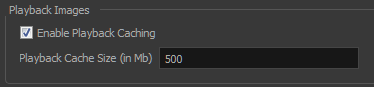
When you select this option, the first run of the playback will store the frames in memory, so the second time around they play in real time. If you have a large scene, 500 Mb may not be enough to hold all the images. In this case, the images will be dropped as new ones are loaded. Increase the value if you have more memory available in your computer.
If you adjust the OpenGl display, such as changing certain display settings (like Bbox selection style) or resizing the view, the frames will be discarded from memory, and must be reloaded.
Import
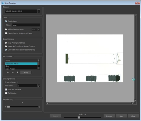
New Twain Scan Interface
A new interface has been designed for Harmony 11 Twain acquisition, combining the best features from the Animate products and Pencil Check Pro. The album concept no longer exists. You can scan multiple drawings by simply continuing to press the Scan button (you will still be communicating with the driver installed for the particular scanner connected). You also have the ability to see a preview of the different vectorization styles. Some features from Pencil Check Pro would be the Page Panning, Scan and Advance, Flip Drawing and the different hold value.
Importing Bitmap Images
A bitmap image is an image composed of pixels that are both size and resolution dependent.
Also, you can choose to import bitmap images on bitmap or vector layers depending on your project.
| 1. | Do one of the following: |
| ‣ | From the top menu, select File > Import > Images. |
| ‣ | In the File toolbar, click the Import Images |
| ‣ | In the Xsheet view, right-click anywhere in the frame area and select Import > Images. |
The Import Images dialog box opens.
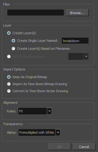
| 1. | In the Files section of the Import Images dialog box, click Browse to find and select one or more images on your computer. |
| 2. | Decide if the bitmap image will go on a new layer or an existing layer. To add the bitmap image to a new layer, go to step 4. To add the bitmap image to an existing layer, go to step 5. |
| 3. | Add the bitmap image to a new layer by selecting the Create Layer(s) option and one of the following options: |
| ‣ | Create Single Layer Named: Creates a layer you can name. |
| ‣ | Create Layer(s) Based on Filenames: Creates a layer based on each unique filename prefix. For example, the filenames a-1.tga, a-2.tga and b-1.tga will create layers name "a" and "b", where "a" has two drawings and "b" has one. When creating a single layer from these three filenames, all three drawings will be inserted in the new layers. |
| 4. | Select the Add to Existing Layer option if you want to place the bitmap image on a layer you select from the list. If only vector |
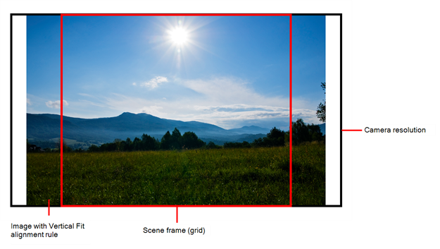
| 5. | In the Import Options section, select the Keep As Original Bitmapoption. In the Alignment section, decide on the size and placement of your image within the camera frame. Depending on the Scene Settings (the height and width in pixels that you chose for your project), an image that you import may be scaled to the point where all its individual pixels become visible. There are three options available in the Alignment section: |
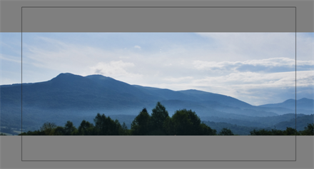
Parameter Description Fit Enlarges or shrinks (but not distorts) the image height to match the full height of the scene grid.
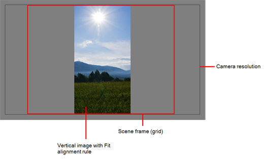
If the image orientation is landscape, this will enlarge or shrink (but not distort) your image width to match that of the scene grid.
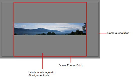
Note that the Fit alignment rule equals the Center Fit rule in the layer properties.
Pan This is the opposite of the Fit parameter. If the image orientation is portrait, its width will be made to match the width of the scene grid. As a result, part of the image’s height will extend beyond the height of the frame. This can be useful if you want to make your background move up and down, or from left to right to make it appear as if the camera is panning, or to actually perform a camera pan.
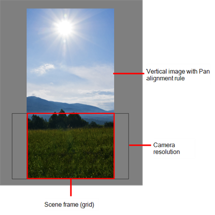
The opposite will apply to a landscape image. Its height will be fit to the scene grid, therefore it is possible that the image will extend beyond the scene grid's boundaries.
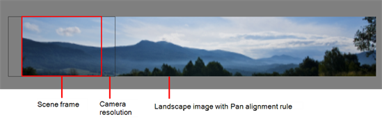
Note that the Pan alignment rule equals the Center First Page rule in the layer properties.
Project Resolution Scales the image in proportion to the scene's resolution. The system looks at the resolution of the bitmap image, for example 4000 x 2000, then compares it to the scene's resolution, for example 1920 x 1080, and adjusts the scale factor in proportion. So, in this example, the bitmap would appear at 208% (4000/1920). If you import a bitmap that is 960 x 540, it will be displayed at 50% (960/1920) of the size of the project resolution.
Note that the Project Resolution alignment rule is equal to the As Is rule in the layer properties.
| 6. | In the Transparency section, select one of the following from the Alpha menu: |
Parameter Description Premultiplied with White
Individual pixels at the edge of an image are blended with white.
Premultiplied with Black
Semi-transparent pixels in the original image are blended with black.
Straight
Pixels at the edge of an image are blended with black, white and greys.
Clamp Colour to Alpha
Premultiplies the colour value with the alpha value. When the colour is clamped to the alpha, the colour value cannot be higher than the alpha value. It calculates the real colour value faster. When the RGB values are multiplied with the alpha value, that is, if you have a pixel of value R=247, G=188, B=29 and the alpha is 50% or the image has a 50% transparency, then the actual RGB values that are output would be half of the amounts listed above.
| 7. | Click OK. |
| 1. | In the Files section of the Import Images dialog box, click Browse to find and select one or more images on your computer. |
| 2. | In the Import Options section, select the Import asToon Boom Bitmap Drawing option. |
| 3. | Decide if the bitmap image will go on a new layer or an existing layer. To add the bitmap image to a new layer, go to step 4. To add the bitmap image to an existing layer, go to step 5. |
| 4. | In the Layer section, select the Create Layer option, and one of the following options to add the bitmap image to a new layer: |
| ‣ | Create Single Layer Named: Creates a layer you can name. |
| ‣ | Create Layer(s) Based on Filenames: Creates a layer based on each unique filename prefix. For example, the filenames a-1.tga, a-2.tga and b-1.tga will create layers name "a" and "b", where "a" has two drawings and "b" has one. When creating a single layer from these three filenames, all three drawings will be inserted in the new layers. |
| 5. | Select the Add to Existing Layer option to place the bitmap image on a layer you select from the list. If only vector |
| 6. | In the Alignment section, decide on the size and placement of your image within the camera frame. Depending on the scene settings (the height and width, in pixels, that you chose for your project), an image that you import may be scaled to the point where all its individual pixels become visible. |
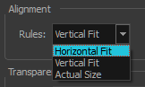
The following three Alignment Rules options are available:
| Parameter | Description |
| Vertical Fit |
Enlarges or shrinks (but not distort) to your image height to match the full height of the scene frame (alignment grid).
|
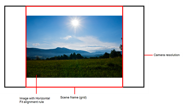
| Horizontal Fit |
Enlarges or shrinks (but not distort) to your image height to match the full width of the scene frame (alignment grid).
|
| Actual Size |
Scales the image in proportion to the scene's resolution. The system looks at the resolution of the bitmap image, for example 4000 x 2000, then compares it to the scene's resolution, for example 1920 x 1080, and adjusts the scale factor in proportion. So, in this example, the bitmap would appear at 208% (4000/1920). If you import a bitmap that is 960 x 540, it will be displayed at 50% (960/1920) of the size of the project resolution. |
| 7. | In the Transparency section, decide how the bitmap image will be antialiased, more specifically, the way the pixels along the edge are blended in the RGBA (red, green, blue, alpha (transparent)) channels. Your bitmap image will exist in the bitmap layer of the newly created drawing element. |
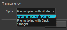
| Parameter | Description |
|
Premultiplied with White |
Individual pixels at the edge of an image are blended with white. |
|
Premultiplied with Black |
Pixels at the edge of an image are blended with black. |
|
Straight |
Pixels at the edge of an image are blended with black, white and greys. |
| 8. | Click OK. |
| 1. | In the Files section of the Import Images dialog box, click Browse to find and select one or more images on your computer. |
| 2. | In the Import Options section, select the Convert to Toon Boom Vector Drawing option. You can choose to encapsulate the bitmap in a symbol by selecting the Create Symbols for Imported Items option. |
| 3. | Decide if the bitmap image will go on a new layer or an existing layer. To add the bitmap image to a new layer, go to step 4. To add the bitmap image to an existing layer, go to step 5. |
| 4. | In the Layer section, select the Create Layer option, and one of the following options to add the bitmap image to a new layer: |
| ‣ | Create Single Layer Named: Creates a layer you can name. |
| ‣ | Create Layer(s) Based on Filenames: Creates a layer based on each unique filename prefix. For example, the filenames a-1.tga, a-2.tga and b-1.tga will create layers name "a" and "b", where "a" has two drawings and "b" has one. When creating a single layer from these three filenames, all three drawings will be inserted in the new layers. |
| 5. | Select the Add Existing Layer option to place the bitmap image on a layer you select from the list. If only vector |
| 6. | In the Vectorization section, decide whether you want to import your image in black and white or grey. |
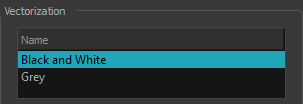
| Parameter | Description |
| Black and White | Vectorizes drawings as a solid black line; creates a 100% vector-based drawing. |
| Grey | Vectorizes your image as a mix of vector contour and greyscale bitmap filling. Lines keep the texture from the scan, and the white of the paper becomes transparent. |
Importing PDF and Illustrator Files as Separate Layers
You can import the different groups/elements of a PDF or Illustrator file as separate layers. For Illustrator files, the import will use the top level group as separate layer names. Deselect this option import PDF or Illustrator file as a single layer.
Colour View
Pencil Line Texture
You can apply a texture on a pencil line.
Pencil lines support texture. Before drawing, you can select or import a texture and apply it to your lines. You can also change it afterward using the Select tool. Textures are independent from pencil templates.
When you import a texture in your pencil styles, it is saved in your scene. If you want to add that texture to a bank that you will be able to reuse in different scenes, you can add that texture to your preferences.
There is a pencil texture palette created in each scene. In order for this palette to be created, you need to draw a pencil stroke using texture. To see it, you need to enable the Advance Palette Lists preference. Once enabled, you will see a palette named pencilstyle_opacity appear in your palette list.
For advanced usage, you can assign a custom palette as your pencil texture palette. All textures used to draw in your scene will be added to this custom palette.
This gives you the ability to save your custom palette at the Environment or Job level if you want to reuse that palette in more than one scene.
| 1. | In the Tools toolbar, select the Pencil |
| 2. | In the Tool Properties view, the preview area displays the stroke that will be produced after you customize the different parameters in the Tool Properties view. Click the arrow button. |

In the Pencil Properties property editor displays.

| 3. | In the Texture section, select a texture for your pencil. |
| 4. | In the Camera or Drawing view, draw your pencil line. |

| 1. | In the Tools toolbar, select the Pencil |
| 2. | In the Tool Properties view, click the arrow button beside the stroke preview area. |
| 3. | In the Pencil Properties editor, click the New Texture |
| ‣ | To delete a preset style, click the Delete Texture |
| 4. | Browse for your bitmap texture file. |
| 5. | Click Open. |
The imported texture is saved in your scene texture list.

| 6. | In the Pencil Properties property editor, select your new texture. |
| 7. | In the Tool Properties view, click the Texture menu and select Rename Texture. |
The Rename Opacity Texture dialog box opens.

| 8. | In the Name field, type the template name and click OK. |
| 9. | In the Camera or Drawing view, draw your pencil lines. |
Game Export
| • | A script named TB_ExportToSpriteSheets creates sprite sheets from the scene’s assets. There is a user interface file that can be linked to this script. |
| • | Added export to EaselJS game engine (HTML5). |
Harmony Cloud
Harmony Cloud is a web-based application that reads Harmony database files in order to carry out most of the same functionality of Control Center remotely—see the Control Center User Guide.
Function View
The Function view has been improved. The Function view is used to edit function curves and parameters. It is a visual graph allowing you to add, remove, and edit keyframes as well and adjusting the velocity. The Function view allows you to display multiple functions in the background as a reference.

| 1. | Open the Function view. |
The Function view is blank until you select the layer containing the functions you want to display.
| 2. | To display a function in the Function view, click on the layer containing the functions to adjust in the Timeline view. |
| 3. | To select the functions you want to edit, select them in the Functions List section. |

When selecting a layer in the Timeline view, all the corresponding functions are displayed. Only the created functions will be displayed. Until a keyframe is added on the function in the Timeline view, it will not be available in the Function view. Enable all the functions you want to see and edit and disable the ones you want to hide.
The Display toolbar allows you to modify how the editing area is displayed, You can hide the grid, disable the synchronization with the current frame, reset the zooming level and normalize the function display by stacking them one over the other to compare them regardless of their value range.
This field displays the current scene frame.
This field displays the value of the selected keyframe.
The arrow button displays the Projection, Bias, Tension and Continuity parameters to adjust the curve around the selected keyframe.

This toolbar allows you to add and delete keyframes, adjust the velocity curve, adjust the segments to motion or stop-motion keyframes and set the velocity to create steps instead of a constant progression.
This toolbar allows you to click on the different function types to enable or disable all the listed functions of that type.
The Value Scale displays the value range for the displayed editing area. It can be referenced to know the value of a keyframe.
The selected keyframe is displayed in red. When selected, the keyframe values are displayed in the corresponding fields.
The Bezier handles can be used to adjust the ease in and ease out of each keyframe. The more the handle is pulled out horizontally, the slower the animation will be. The more the handle is pulled out vertically, the faster the animation will be.
The thin line going from keyframe to keyframe is the actual curve. The section of a curve located between two keyframes is called segment.
The Frame Scale displays the frame range for the displayed editing area. It can be referenced to know the current frame of a keyframe.
Script Help View
The Script Help view provides you with information and object list to create your own custom script to automate your most recurrent operations in Harmony.

The Category tabs allow you to select the category of information you are looking for:
| • | Script |
| • | ScriptModule |
| • | Expression |
The Search toolbar allows you to type in a variable or object name and quickly find it in the list to access its information. Press Enter/Return to validate your search query.
This lists all the objects and variables available for scripting.
The Information window details the information, parameters and type related to the selected object.
Sketch Module
![]()
The Sketch module is a component of the Stage module. It contains the essential tools to animate frame-by-frame drawings and paint them. It allows you to add layers, animation, paint and adjust the timing. There are no effects, camera or other compositing tools included in this module. It allows you to focus on the paperless animation tasks at hand without being distracted by other features that are not necessary to your work.
To learn more about the Sketch module, see the following guides:
| • | Fundamentals Guide |
| • | Sketch Guide |
| • | Preferences Guide |
Draw Module
![]()
The Draw module is a component of the Stage module. It contains all the tools necessary to create a paperless frame-by-frame animation project. There is no node system included in this module and only the basic essential effects are included in it. Contrary to the Stage module, instead of creating effects in the Network view, you simply create them in the Timeline view. Draw also includes all the scene setup and camera features for you to do the compositing for your project.
To learn more about the Draw module, see the following guides:
| • | Fundamentals Guide |
| • | Draw Guide |
| • | Preferences Guide |
Miscellaneous changes
| • | Backward Compatible: Allow scenes that were optimized in 10.3 to be openable in 11. |
| • | Flash: You are no longer asked if you want the Flash preferences and shortcuts the first time you start the application. |
| • | Magnifier Option: The Magnifier option in Brush and Pencil tool properties has been removed. |
| • | Colour Protection: There is a keyboard shortcut for Respect Colour Protection: Shift + S. |
| • | All New Icons: There are brand new icons in Harmony. |
| • | Dark Interface: There is a preference to change the interface from the new dark look to the original light colours. This preference is in the General tab. You need to restart the application. |
| • | Standalone or Database: On both Mac and Windows you can choose to install as standalone or database. You can create the appropriate apps or shortcuts for Control Center, Draw, Stage, Paint, etc. You must have the appropriate license for each app. For example, you can install as standalone but using the license tokens, restrict the ability to work in other modules. |
| • | Toolbars: It is no longer possible to drag and drop a toolbar in a view like in version 9.2. |
| • | Mental Ray: There is support for Mental Ray renderer in Maya for non-server version of our scripts. |
| • | Stage File: Added preference to optimize the scene's stage file to make it smaller in the database. Keyframes and handles on Ease and Bezier curves are compressed, but not for 3D path and Quaternion. Unused anonymous functions are removed. |
| • | Scene Name: The Welcome Screen has Scene Name instead of Project Name |
| • | Mipmapping for Bitmap Layers: A new OpenGL preference named Enable Mipmapping for Bitmap Layers lets you disable it if you are using an older graphics card that does not support mipmapping for bitmap layers. |
| • | Renamed Preference: The Create Posed Deformer in Create Deformation Above/Under option in the Deformation tab has been renamed: Automatically Create new Deformer Structure for each Pose/Drawing |
| • | Multithreading: Rendering is using more multithreading so it is faster than before. |
| • | Database Utility: The database utility has been consolidated to remove duplicate drawings and clean the .stage file. |
| • | Particle Example Modules: These modules have been moved from the All Modules tab to the Particle-Examples tab. Also the menu items in Insert don’t offer all the examples. If you want to use or look at the particle examples, they are available from the Module Library view. |
| • | Control Center: The Animator and Supervisor types of user were added in the Control Center. The Animator type cannot delete jobs or scenes but can create, copy, and release their scene’s lock. |