Lecture Notes
This topic is divided as follows:
| • | Animating a Layer |
| • | Animated Layers and Pegs |
| • | Adding and Deleting Keyframes |
| • | Motion and Stop-motion Keyframes |
| • | Animating the Camera |
| • | Modifying a Path in the Camera View |
| • | Modifying a Path in the Timeline View |
| • | Copying and Pasting a Motion |
| • | Adjusting the Velocity |
Animating a Layer
This section describes the basics of animating a layer.
Harmony’s wide range of features let you produce accurate trajectories. However, before doing this, you must learn the basics of animating a layer by creating a simple motion, and practice everything you learn in this lesson.
There are two key elements in creating a motion:
| • | Animate Mode |
| • | Animating a layer |
Animate Mode
When you enable this mode when you animate layers, Harmony will apply a transformation to the current frame. Otherwise, a transformation is applied on the entire layer instead of only the current frame.
To enable the Animate Mode:
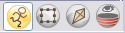
| 1. | In the Tools toolbar, click the Animate Mode |
Animating a Layer
Follow these steps to perform a basic layer animation.
To animate a layer:
| 1. | In the Tools toolbar, select the Transform |
| 2. | In the Transform Tool Properties view, make sure that the Peg Selection Mode |
| 3. | In the Tools toolbar, click the Animate Mode |
| 4. | In the Timeline view, go to the first frame. |
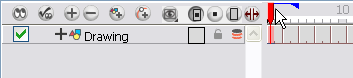
| 5. | In the Camera view, select the element to animate and move it to its first position. |
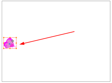
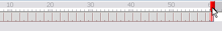
| 6. | In the Timeline view, go to the frame on which you want to set the second position. |
| 7. | Play back |
Enabling Playback
To see your motion animations in the Top, Side or Perspective views while you play back, you must turn on the Playback option.
To enable the Playback option:
| ‣ | From the top menu, select Play > Enable Playback > Top View, or Side View or Perspective View. |
Animated Layers and Pegs
To animate the position of your drawings you need to create motion paths. Motion paths are trajectories on which you can hook your drawing objects. You will use keyframes to record the key positions along the trajectory.
There are two ways in which to create motion paths: animated layers and pegs. Animated drawing layers and pegs have different purposes.
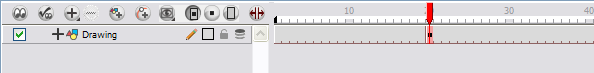
Animated Layers
You can create a motion path directly on your layers.
Drawing layers can house drawings and symbols. Also, in that same layer you can create a motion path using keyframes and all the artwork contained in the layer will follow.
You can control and define your trajectory using several different parameters. These parameters are:
| • | X, Y and Z positions |
| • | Angle (rotation) |
| • | Skew |
| • | X and Y scales |
Each parameter has its own function curve where you can add keyframes and control the easing.
Do not worry about using graphs and function curves if you are not familiar with this concept. Harmony has a series of easy-to-use tools for visually controlling your trajectories in the Camera view.
To animate a simple object such as an arrow in flight or a wheel spinning, you can use the integrated trajectory. Also, each part of a cut-out puppet will be animated directly on the drawing layer.
Pegs
A Peg layer is a trajectory that contains no drawings on which you can hook your drawings.
Why Use a Peg Layer?
A peg is composed of many customizable parameters. These parameters are:
| • | X, Y and Z positions |
| • | Angle (rotation) |
| • | Skew |
| • | X and Y scales |
| • | 3D rotation (when the 3D option is enabled) |
You can control a peg’s trajectory the same way as the animated drawing layer.
A peg layer is mainly used to control a series of drawing layers. If you have several drawing layers, such as clouds or a character split into many parts, you can hook those to a peg layer and have them follow a trajectory as a unit. When building a puppet, most of the time you will add a master peg to control your puppet as one object.
The Origin of a Peg
Pegs have been used for a long time in the traditional animation process, mainly for registration purposes. Peg holes at the bottom (or top) of animation paper are used to keep all of the sheets even and at the same registration.
There are three peg holes in regular animation paper. The centre peg hole is circular while the left and right ones are rectangular. These rectangular peg holes are located on each side of the page, and four inches away from the centre peg hole.
To keep the drawings together, the animator uses a peg bar. This peg bar has three pins that correspond to the shape and location of the peg holes. Peg bars are normally found at the bottom and top of animation discs.
Before digital compositing, the peg bars were also used to move levels under the camera stand. They were the equivalent of digital trajectories. Harmony makes use of these concepts to create animation and camera moves.
Adding a Peg to the Timeline
To add a peg:
| 1. | Select the layer on which you want to attach a peg. |
| 2. | Do one of the following: |
| ‣ | From the Timeline View layers toolbar, click the Add Peg |
| ‣ | From the top menu, select Insert > Peg. |
| ‣ | Right-click (Windows) or [Ctrl]+Click (Mac OS X) on the layer and select Add > Peg. |
| ‣ | In Harmony, select a Peg module from the Module Library and drag it to the Network view. |
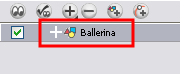
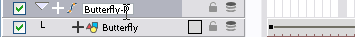
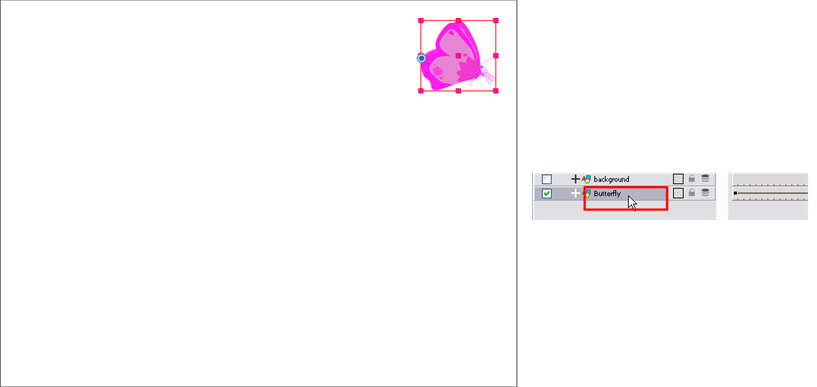
The layer that was originally selected becomes a child of the new parent Peg layer. The new Peg layer automatically takes the name of its child layer, with the addition of the suffix -P.

| 3. | If you intend to add multiple pegs or if the layer name that was added to the peg does not accurately represent the content of the Peg layer, you can rename it. Clicking the layer name and type in a new name. Or double-click the layer and type a new name into the dialog box. |
| 4. | If you did not create your peg layer directly above the layer you intended on parenting it to, then drag the layer you want to attach to the peg and drop it directly below the Peg layer. The indentation of the layer below the Peg layer indicates whether it was correctly attached or not. |

Layer Parameters
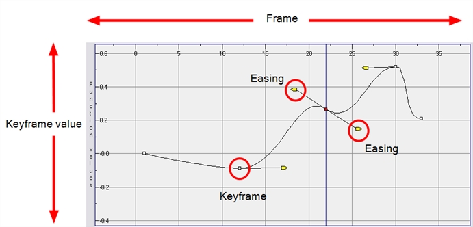
A layer is composed of many customizable parameters, such as the X, Y and Z positions, angle (rotation), skew and scales. Each parameter has its own function. A function is a mathematical formula expressing the relation between position values. You can view each function on a graph as a simple curve such as this one.
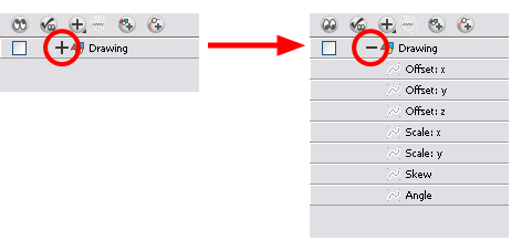
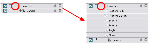
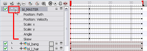
To display the Layer parameters in the Timeline view:
| 1. | Do one of the following: |
| ‣ | In the Timeline’s left side, click the Expand |
| ‣ | To display the functions of a selected layer, select View > Show Functions from the Timeline View menu. |
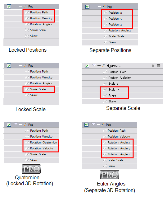
| 2. | There are six options available for setting up function parameters: |
| ‣ | Locked Positions (3D Path) |
| ‣ | Separate Positions |
| ‣ | Locked Scales |
| ‣ | Separate Scales |
| ‣ | Quaternion (3D Rotation) |
| ‣ | Euler Angles (3D Rotation) |
Layer Preferences
You can set the preferences to suit your way of working. In your general preferences, enable Default Separate Positions to get separate X, Y and Z positions, or disable it to get a 3D path. The 3D path is set by default. Enable the Default Separate Scale to get separate X and Y scales. It is highly recommended that you use default separate scales.
You have to lock or unlock your functions before starting the animation. When you lock or unlock parameters, this does not convert the functions from one to the other, but creates new ones.
This topic is divided as follows:
| • | 3D Path |
| • | Separate Positions |
| • | Locked Scales and Separated Scales |
| • | Setting the Parameters |
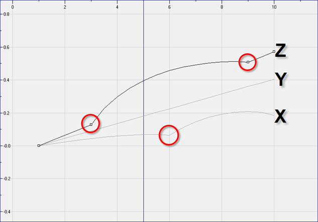
3D Path
In a 3D Path, the X, Y and Z curves are locked together and controlled by a single velocity function. When you add a keyframe, it is added on all three trajectories at once, as is the velocity. This is very useful for long, smooth trajectories.
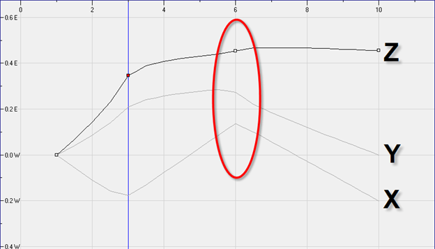
Separate Positions
When the Separate Positions option is used, the X, Y and Z curves are independent and have velocity controls directly on their function curve. This is useful when you want to set keyframes on one of the curves without affecting the others.
Locked Scales and Separated Scales
When using the scale function, you can have a single function curve controlling both the vertical and horizontal scale, or have the two scales separate. This means that when using the single function, the values will be the same for the X (horizontal) and the Y (vertical) axes, enabling a uniform size change without distortion. However, if you separate the scale functions, you will be able to squash, stretch and skew your elements.
Setting the Parameters
You can set the parameters for 2D motion.
To set the parameters:
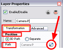
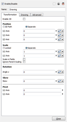
| 1. | In the Timeline view, double-click the layer on which you want to set the parameter. |
The Layer Properties editor opens.
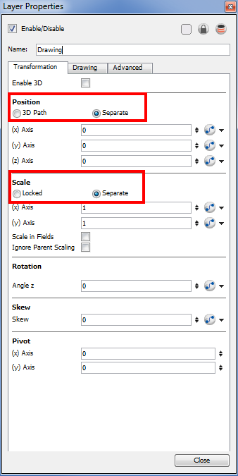
| 2. | Select the Transformation tab. |
| 3. | In the Position section, select the 3D Path or Separate option. |
| 4. | In the Scale section, select the Locked or Separate option. |
| 5. | Click Close. |
Adding and Deleting Keyframes
You can create a keyframe in several different ways. You can add a coordinate keyframe, position keyframe or a keyframe along with your drawing duplication.
| • | Creating a Keyframe |
| • | Adding a Keyframe and Duplicating a Drawing Simultaneously |
| • | Deleting Keyframes |
Creating a Keyframe
You can create a keyframe without a drawing. This adds new coordinate points but the drawing in the layer stays the same.
To create keyframes:
| 1. | In the Timeline view, select the cell on which you want to add a keyframe. |
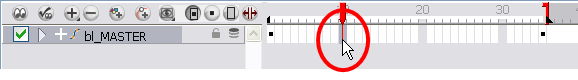
| 2. | Add a keyframe by doing one of the following: |
| ‣ | From the top menu, select Insert > Keyframe. |
| ‣ | Right-click (Windows) or [Ctrl]+Click (Mac OS X) on the selection and select Add Keyframe. |
| ‣ | Press [F6]. |
| ‣ | In the Timeline View toolbar, click the Add Keyframe |
| ‣ | If the Animate mode is enabled in the Camera view, a keyframe is automatically created on the current frame. |
Adding a Keyframe and Duplicating a Drawing Simultaneously
You may want to duplicate your drawing at the same time if you need to modify it and do not want to modify the original.
To create a keyframe and duplicate your drawing at the same time:
| 1. | In the Timeline view, select the cell containing the drawing where you want to add a keyframe and duplicate. |
| 2. | To add a keyframe and duplicate, do one of the following: |
| ‣ | From the top menu, select Insert > Keyframe and Duplicate Drawing. |
| ‣ | Right-click (Windows) or [Ctrl]+click (Mac OS X) on the selection and select Insert Keyframe and Duplicate Drawing. |
| ‣ | Press [F6]. |
Deleting Keyframes
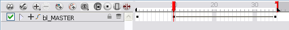
To delete a keyframe, do one of the following:
| ‣ | Use the Transform |
| ‣ | In the Timeline view, click a keyframe, right-click (Windows) or [Ctrl]+Click (Mac OS X) and select Delete Keyframes, or press [F7]. |
| ‣ | From the top menu, select Animation > Delete Keyframe. |
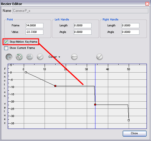
Motion and Stop-motion Keyframes
Interpolation is the computer-generated motion between two keyframes. Some animators and compositors like to create their own in-betweens, while others like to have the computer do it. Harmony lets you have stop-motion and motion keyframes.
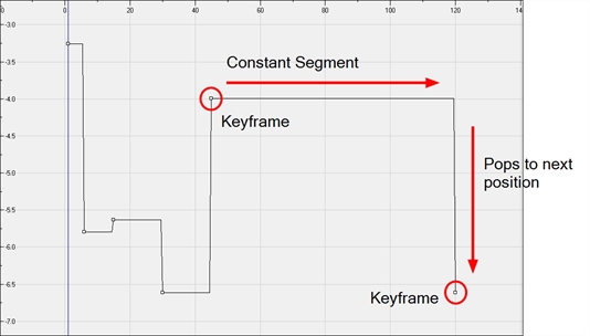
Stop-motion Keyframes
A stop-motion keyframe means there is no computer-generated motion between two keyframes. The segment is constant or flat.
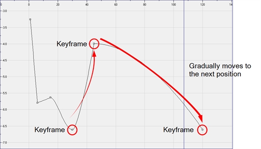
Motion Keyframes
A motion keyframe means that there is computer-generated motion between two keyframes. The segment has a variation over time.
Switching between Motion and Stop-motion Keyframes
You can switch a keyframe from stop-motion to motion at any time in the Timeline view and Function Editor.
To switch between Motion and Stop-Motion in Timeline View:
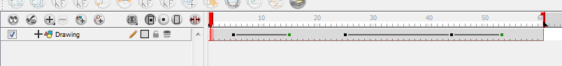
| 1. | On the right side of the Timeline, select one or more keyframes to be modified. |
| 2. | To switch between motion and stop-motion, do one of the following: |
| ‣ | Right-click (Windows) or [Ctrl]+Click (Mac OS X)) on the selected keyframes and select Set Motion Keyframes or Set Stop-Motion Keyframes. |
| ‣ | Press [Ctrl] + [K] (Windows/Linux) or [⌘] + [K] (Mac OS X) or [Ctrl] + [L] (Windows/Linux) or [⌘] + [L] (Mac OS X). |
| ‣ | In the Timeline View toolbar, click the Motion Keyframe |
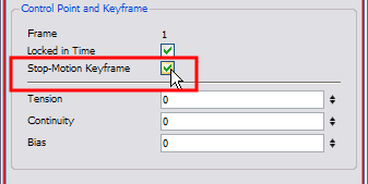
| ‣ | In the Camera view, select the keyframe to convert. In the Coordinates and Control Point view, select/deselect the Stop-Motion Keyframe option. |
To swtich between motion and stop-motion keyframes in the Function Editor:
| 1. | Open the Function Editor. |
| 2. | In the Timeline view, double-on the layer that contains the keyframes that you want to convert. |
The Layer Properties dialog box opens.
| 3. | In the Transformation tab, click the Function Editor |
OR
| 1. | In the Timeline view, click the Expand Function |
| 2. | Select one or more keyframes to modify on the Function Curve. |
| 3. | Select or deselect the Stop-Motion Keyframe option to set a stop-motion or motion keyframe. |
Setting a Different Colour for Stop-motion and Motion Keyframes
In the Preferences dialog box, you can set a different colour for your stop-motion keyframes in order to create a greater visual difference in the Timeline view.
To set the stop-motion keyframe colour:
| 1. | Open the Preferences dialog box by pressing [Ctrl] + [U] (Windows/Linux) or [⌘] + [U] (Mac OS X). |
| 2. | Select the General tab. |
| 3. | In the Colours section, click Edit Colours. |
| 4. | In the Colours window, select the Exposure Sheet tab. |
| 5. | In the Others section, click the Stop Motion Keyframe swatch. |
| 6. | In the Select Colour window, select a new colour. |
| 7. | Click OK to close the Select Colour window. |
| 8. | Click OK to close the Colours window. |
| 9. | Click OK to close the Preferences dialog box. |
Animating the Camera
Just as in a live-action film, scenes are not only composed of characters moving around in a static camera field, but also of camera movements. Although it is not always something that we think about, often it is the exact opposite—the character is static while the camera moves through elements on the stage. Camera pans, jumps, cuts and zooms are as important to storytelling as the story itself.
Harmony has a camera that can move along the X, Y, and Z axes. Having the camera move on the Z-axis offers the possibility to create truck in and truck out, as well as multiplane camera moves. The default camera position is centred and backed up to 12 fields.
The Basic Camera Move
The camera is treated the same way as any other element. The same tools and selection modes are used to offset or animate it. To animate the camera, you need to connect it to a peg element.
This means that you can animate the camera visually, with the function curve, or by typing values in the Xsheet column.
To add a camera with a peg to your scene:
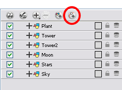
| 1. | If you do not already have a camera layer, do one of the following: |
| ‣ | From the top menu, select Insert > Camera. |
| ‣ | From the Timeline view layers toolbar, click the Add Layers |
| ‣ | In Harmony, select a Camera module from the Library view and drag it to the Network view. |
A new camera layer is added to the scene and appears in the Timeline view.
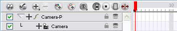
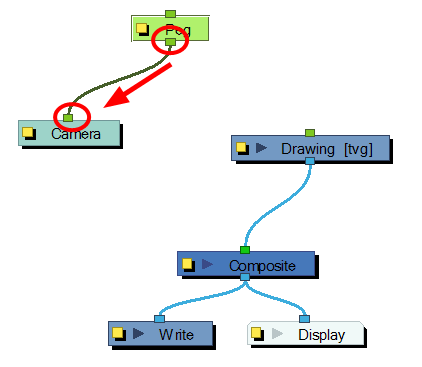
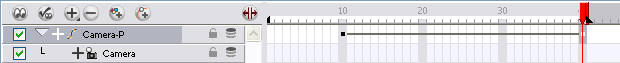
| 2. | From the Timeline View Layer toolbar, click the Add Peg |
A Peg layer appears directly above the Camera layer. The Camera layer is automatically attached to it.
The Peg layer automatically takes the name of the camera and adds the suffix -P to indicate that it is a Peg layer, for example Camera-P.
If the new Peg layer did not appear directly above the camera, you may have clicked elsewhere in the scene, which deactivated the layer on which you want to add the Peg layer.
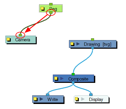
| ‣ | Select the Camera layer and drag and drop it under the new Peg layer. Or delete the misplaced Peg layer, select the Camera layer and click the Add Peg |
| ‣ | In Harmony, you can select a Peg module from the Library view and drag it to the Network view. Then you can connect the peg’s output port to the camera’s input port. |
You are now ready to animate your camera.
Make use of both the Top and Camera views while making camera moves. You can open this view is one of two ways:
| ‣ | From the top menu, select Windows > Top. |
| ‣ | From any existing window already open in your project, click the Arrow |
The Top view appears as a tab in that view.
To animate the camera:
| 1. | Make sure both the Animate |
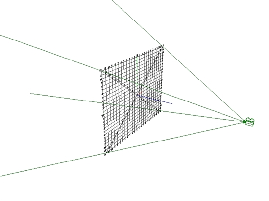
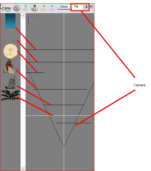
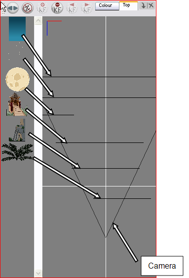
| 2. | In the Top, Side or Camera view, select the camera (the large V-shape on the right side) and move it to the desired position. |
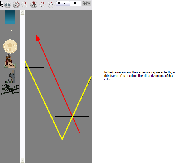
| 3. | In the Camera view, the camera is represented by a thin frame. You need to click directly on one of the edge. |
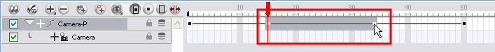
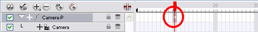
| 4. | In the Timeline view, click on a cell in the Camera Peg layer where you would like the camera move to begin. |
| 5. | Right-click (Windows) or [Ctrl]+Click (Mac OS X) and select Insert Keyframe. |
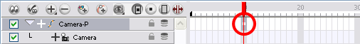
A keyframe appears in that cell. Any frames preceding this keyframe cell will hold the same camera position as in this keyframe.
| 6. | Click on another cell a bit further down your scene’s Timeline. This is where the camera move will end. |
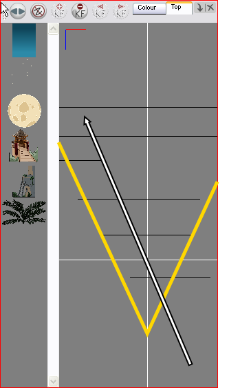
| 7. | Select the camera in the Top view and move it to the desired position. |
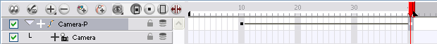
A second keyframe appears and a line is created between the two frames to indicate that the subsequent motion between the frames will be calculated and rendered by the program.
| 8. | Play back |
You are now ready to animate your camera.
It is recommended to use both the Top and Camera views while making camera moves. You can open this view is one of two ways:
| • | From the top menu, select Windows > Top. |
| • | From any existing window already open in your project, click the arrow |
To animate your camera:
| 1. | Make sure that the Animate |
| 2. | In the Top, Side or Camera view, select the camera and move it to the desired position. |
| ‣ | In the Top and Sive view, the camera is the large V cone. You need to click directly on one of the edge. |
| ‣ | In the Camera view, the camera is represented by a thin frame. You need to click directly on one of the edge. |
| 3. | In the Timeline view, click on a cell in the Camera Peg layer where you want the camera move to begin. |
| 4. | Right-click and select Insert Keyframe. |
A keyframe appears in that cell. Any frames preceding this keyframe cell will hold the same camera position as in this keyframe.
| 5. | Click on another cell, further down your scene's Timeline, where you want the camera move to end. |
| 6. | Select the camera in the Top view and move it to the desired position. |
A second keyframe appears and a line is created between the two frames to indicate that the subsequent motion between the frames will be calculated and rendered by the program.
| 7. | Play back |
Modifying a Path in the Camera View
Although the example in the Animating the Camera section seems simple enough, camera moves and motion paths can become complex, especially with moves through 3D space. That is why Toon Boom has developed a way to view your camera’s path and make adjustments to it from both a 2D and 3D perspective.
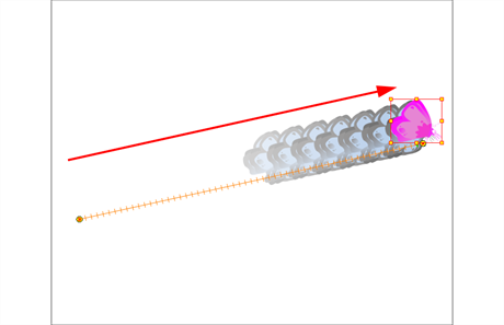
Displaying a Path in the Camera View
You can display the trajectory of a motion path when you select an object in the Timeline or Camera view.
To view the layer’s trajectory using the Control command:
| 1. | Verify that the Camera view (click its tab) is selected and that the layer whose trajectory you want to display is selected in the Timeline view. |
| 2. | From the top menu, select View > Show > Control or press [Shift] + [F11]. |
To hide the layer’s trajectory:
| 1. | Verify that the Camera view (click on its tab) is selected and that the layer that you wish to hide the trajectory of is selected in the Timeline or Camera view. |
| 2. | From the top menu, select View > Show > Control or press [Shift] + [F11]. |
| 3. | If you want to hide all trajectories without selecting any layer, select View > Hide All Controls or press [Shift] + [C]. |
Shaping a Path
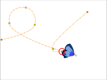
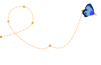
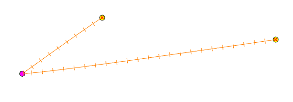
A motion path is as easy to manipulate as shaping the vector points of a drawing layer in the Camera view. One important concept to understand is that a trajectory contains both keyframes and control points. Both can be used to shape a path, each have their own significance and behaviour, however only keyframes appear in the Timeline view.
| • | Keyframe: A marker that signifies a change (size, position, direction, etc.) along the normal of a path or function, and has an exact position and frame. |
| • | Control Point: Has a position but no fixed frame or timing. It is mainly used to deform a trajectory. There are no velocity handles available on a control point. The velocity segments are set between keyframes only, making curves and trajectories much smoother. Control points can only be added on a 3D path. |
To resize an entire animation path, so it fits into your scene’s composition better, convert the animation into a Symbol, then resize the Symbol.
Adding Control Points
A control point has a position but no fixed frame or timing. It is mainly used to deform a trajectory. There are no velocity handles available on a control point. The velocity segments are set between keyframes only, making curves and trajectories much smoother.
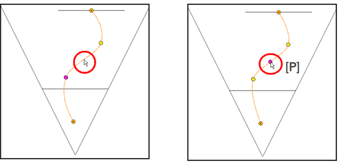
A control point will not show in the Timeline view because it has no precise frame on which to be displayed. It appears on the function curve and in the Camera view. There are different ways to add control points:
| • | Display the trajectory in the Camera view and press [P]. |
| • | Add a keyframe on the function curve and deselect the Lock in Time option. |
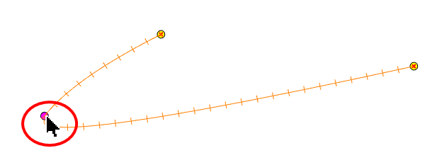
The control point is displayed as a circle.
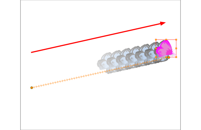
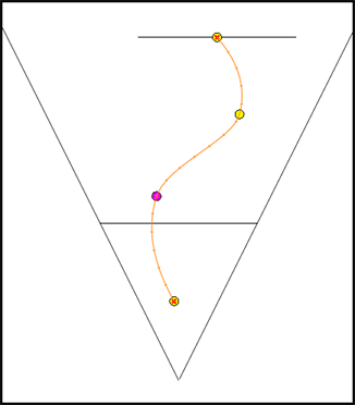
You can display your trajectories in the Camera, Top and Side views to better understand the way the elements move in your scene. This also makes it easier to modify them. You can display a peg or layer’s controls to see where your elements are going, modify the curve, and add keyframes and control points.
To add a control point on a trajectory:
| 1. | In the Timeline or Camera view, select the peg or layer on which you want to add a control point. |
| 2. | If the selected element’s trajectory is not displayed, select View > Show > Control in the top menu or press [Shift] + [F11]. |
The Trajectory appears in the Camera, Top, Side and Perspective views.
| 3. | Add control points on a 3D path trajectory by placing the cursor where you want to add the point and pressing [P]. |
Adjusting the Tension, Bias and Continuity
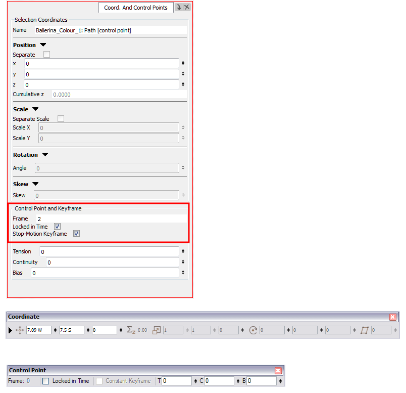
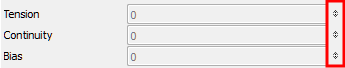
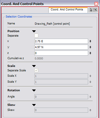
You can edit keyframes and control point parameters, such as the position, continuity, bias, tension, and lock in time using the Coordinates and Control Point view.
Each time a keyframe or control point is selected in the Camera, Timeline or Xsheet view, its parameters appear in the Coordinates and Control Point view. You can also see the same information in the Coordinate and Control Point toolbars.
You can adjust these parameters on existing control points and keyframes by selecting the point in the Camera view with the Transform ![]() tool.
tool.
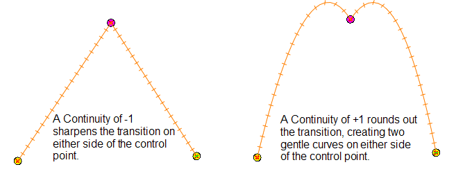
| • | Continuity controls the smoothness of a transition between the segments joined by a point. |
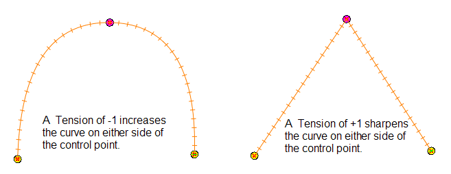
| • | Tension controls how sharply the path bends as it passes through a control point or keyframe. |
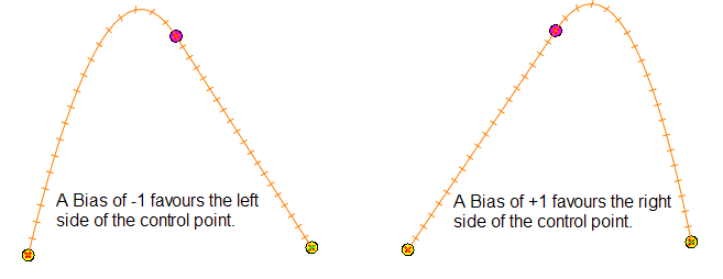
| • | Bias controls the slope of the path so that it flows towards one side of the motion point or the other. |
To adjust the Continuity, Tension and Bias parameters:
| 1. | In the Tools toolbar, select the Transform |
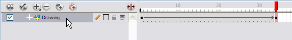
| 2. | In the Timeline view, select the layer that contains the parameters you want to adjust. |
| 3. | In the top menu, select View > Show > Control or press [Shift] + [F11] to display the trajectory. |
| 4. | In the Camera view, select a control point or keyframe. |
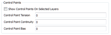
| 5. | In the Coordinates and Control Points view, adjust the Continuity, Tension and Bias parameters. |
If you find that you are using the same Continuity, Tension and Bias settings, you can set a preference to remember your settings.
If you find that you are using the same Continuity, Tension and Bias settings, you can set a preference to remember your settings.
To adjust the control point preferences:
| 1. | From the top menu, select Edit > Preferences (Windows) or Harmony > Preferences (Mac OS X). |
The Preferences dialog box opens.
| 2. | Select the Camera tab and adjust the parameters in the Controls Points section. |
Modifying a Path in the Timeline View
When you select a peg or drawing layer in the Camera view and move it around, Harmony will automatically create the corresponding function curves. If you want to modify these curves, you can always do it through the Peg or Layer parameters in the Timeline view.
Creating a Function
To create the function curve in the Timeline view:
| 1. | Double-click a drawing or peg layer. |
The Layer Properties dialog box opens.
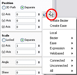
| 2. | Identify the section of the type of function that you want to create. |
| 3. | Click the arrow at the end of the corresponding row and select Create Bézier or Create Ease. |
Adding and Deleting Keyframes in the Timeline View
To add a keyframe:
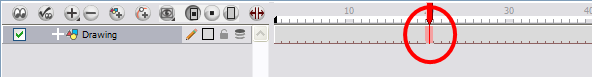
| 1. | On the right-hand side of the Timeline, select a cell on the layer’s function that you want to animate. |
| 2. | Right-click (Windows) or [Ctrl]+Click (Mac OS X) the selected cell and select Insert Keyframe or press [F6]. |
To delete a Keyframe:
| 1. | On the right side of the Timeline, select a cell that contains the keyframe you want to delete. You can [Shift]+click several keyframes to select a group before deleting the keyframes. |
| 2. | Right-click (Windows) or [Ctrl]+Click (Mac OS X) on the selected keyframe and select Delete Keyframes. |
Changing Keyframe Values
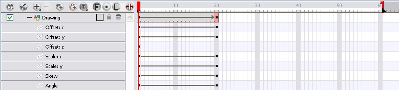
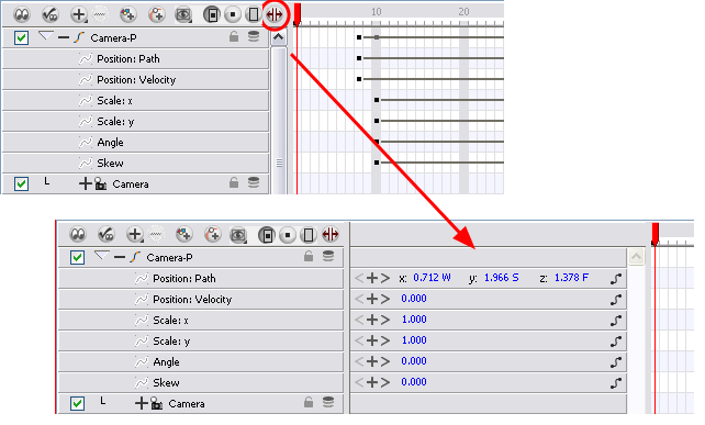
To change the keyframe values in the Timeline:
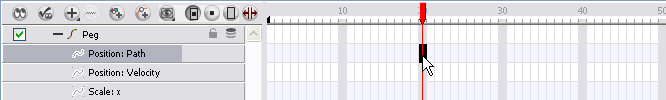
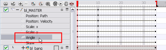
| 1. | Open the layer’s parameters by clicking the Expand |
| 2. | Click the Show/Hide Data view |
| 3. | Select the parameter that you want to create a function curve for: Path, Velocity, Scale; x or y, Angle, or Skew. For this example, we will use Velocity. |
| 4. | Pass the cursor over the blue number value of the parameter layer being modified. |
| ‣ | Wait until the cursor changes to a white hand with a two-way arrow and then drag the hand slightly to the left or right to decrease or increase the value. |
![]()
OR
| ‣ | Click directly on the blue number and enter a value into the field that appears. |
| ‣ | If you selected the keyframe in the Camera view, you can modify the values in the Coordinate and Control Points view. |
A function automatically is created as soon as the values have changed from zero.
In Harmony, you can see the same information in the Coordinates and Control Points view.
| 5. | Play back |
Copying and Pasting a Motion
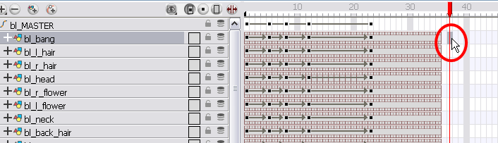
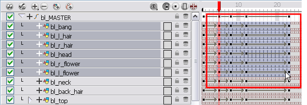
In the Timeline view, you can easily drag keyframes to change the animation timing, delete them, cycle them, and even copy them. You can use the Paste Cycle and Paste Reverse feature to cycle your selection including keyframes and drawings.
Pasting Cycles
If you want to cycle a portion of an animation, you can use the Paste Cycle command.
To cycle a portion of an animation:
| 1. | In the Xsheet or Timeline view, select the cell range and keyframes to loop. |
| 2. | From the top menu, select Edit > Copy. |
| 3. | In the Xsheet or Timeline view, select the cell on which you want your cycles to start. |
| 4. | From the top menu, select Edit > Paste Cycle or press [Ctrl] + [/] (Windows/Linux) or [⌘] + [/] (Mac OS X). |
The Paste Cycle dialog box opens.
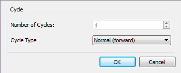
| 5. | In the Number of Cycles field, increase or decrease the number of cycles you want to paste. |
| 6. | In the Cycle Type, select the type of cycle you want to paste. |
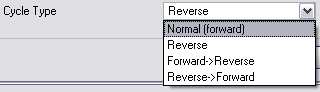
| ‣ | Normal (forward): Pastes your selection as it is, starting with the first cell and ending with the last. |
| ‣ | Reverse: Pastes your selection reversed, starting with the last cell and ending with the first. |
| ‣ | Forward > Reverse: Pastes your selection as a yo-yo, starting with the first cell, going to the last one and ending with the first cell. |
| ‣ | Reverse > Forward: Pastes your selection as a reversed yo-yo, starting with the last cell, going to the first one and ending with the last cell. |
Reversing the Animation Flow
You can reverse the flow of your animation using the Paste Reverse command.
To reverse the animation flow:
| 1. | In the Xsheet or Timeline view, select the cell range and keyframes to paste inverted. |
| 2. | From the top menu, select Edit > Copy. |
| 3. | In the Xsheet or Timeline view, select the cell on which you want your cycles to start. |
| 4. | From the top menu, select Edit > Paste Reverse or press [Ctrl] + [.] (Windows/Linux) or [⌘] + [.] (Mac OS X). |
Adjusting the Velocity
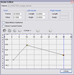
To add ease in and ease out on your motion paths, you can display the function curve and modify the Bezier or Ease curve. To apply an ease to multiple functions and keyframes, you can use the Set Ease For Multiple Parameters script and set the amount desired.
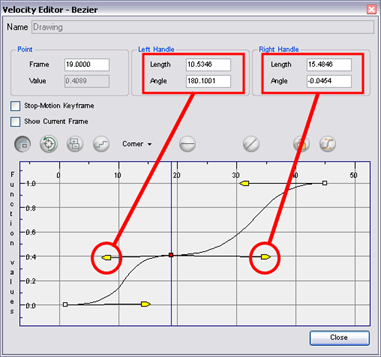
The Velocity, or ease, is used on motion keyframes. The Velocity has to be adjusted directly on the function curve in either the Function view or the Function editor. When a keyframe is selected, easing values appear in the right handle and left handle fields, as well as Bezier handle or Ease wheel controls on each selected keyframe. Pull on them to adjust the ease in and ease out, or type values in the fields.
To display the velocity curve:
| 1. | In the Timeline view, click the Expand |
| 2. | Double-click the desired function. |
The Function Editor opens.
The editor will not be displayed if the function does not already exist. You can reshape the function using either the Bézier or Ease controls.
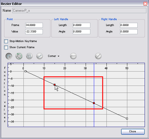
To reshape a function using Bézier controls:
| 1. | Select a keyframe. |
| 2. | Drag the handles to modify the shape of the curve. |
| 3. | The Continuity options influence how you can move the handles: |
| ‣ | Straight: Lets you move the handles together, maintaining the same angle to the point. |
| ‣ | Corner: Lets you move the handles independently. |
| ‣ | Smooth: Lets you move the handles together, maintaining the same distance and angle to the point. |
To hold the same value over several frames:
| 1. | Click the Hold Value Editor |
The Hold Value editor opens.
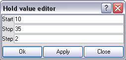
| 2. | In the Hold Value Editor, enter the following values: |
| ‣ | Start: Enter the starting frame for the effect. |
| ‣ | Stop: Enter the last frame for the effect. |
| ‣ | Step: Enter the number of frames to hold the value. |
The function curve is updated based on the values you entered.
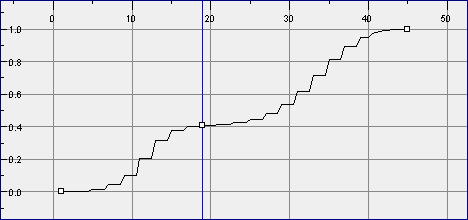
You can reshape the curve to create a linear velocity, so that the values are interpolated (tweened) consistently between keyframes. That is, there is no acceleration in the effect.