Network Navigation and Basic Rules
The basic rules of the Network view are quite simple. Once you understand them, a lot can be accomplished.
Related Topics
| • | About Modules |
| • | Input and Output Ports |
| • | Adding Modules |
| • | Composite Module |
| • | Organizing Modules |
| • | Connecting and Disconnecting Modules |
| • | Cable Styles |
| • | Navigator Display |
| • | Panning the Network View |
About Modules
Each element in the Network view is called a module. There are several different types of modules:
|
Module |
Description |
|
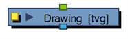
| Drawing |
|
Transfers drawing information. |
| Effect |
|
Processes effects on drawings and transfers drawing information. |
| Input/Output |
|
Act as the interface between each module and network. |
| Move |

|
Controls the camera and element transformations over time. |
| Compositing |

|
Combines multiple source images. |
Input and Output Ports
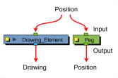
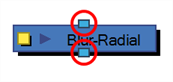
Each module has an input port at the top and an output port at the bottom. Some are blue and others are light-green or bright green.
| • | Blue indicates drawing information. |
| • | Light Green indicates position and movement. |

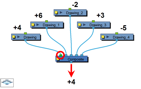
| • | Bright green shows the element on top of the composition and outputs that element’s Z position to the Composite module. When many elements have different Z positions (multiplane, different distances from the camera) and are placed through a Composite module that flattens them together (producing one image with one Z value), the system needs to give a Z position to this new image. It uses the bright green port information. |
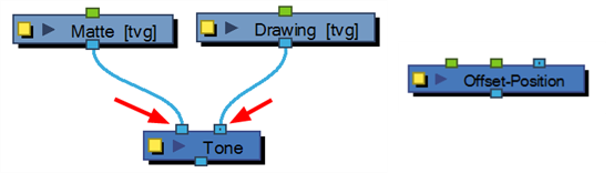
Finally, some modules contain more than one Input port. These are usually Effects modules needing different drawing or position information in order to perform their calculation. When the two ports are blue, the Drawing is on the right and the Matte is on the left. If it is light green, the drawing needs extra position information.
Viewing Port Information
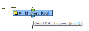
On each port is a tooltip which displays the source of in-ports and the destination(s) of the out-ports.
To display port information:
| ‣ | Hover your cursor over a port. |
The port's tooltip displays source and destination information.
Navigating the Network View
You can navigate to the parent or child module of the selected module or selected cable in the Network.
To navigate the Network view:
| ‣ | In the Network view, select a module or cable, and press [Ctrl] + [Up]/[Down] arrows. |
Adding Modules
Each module used to build a network is available in the Module Library view. In addition, each time you create a layer from the Timeline or Xsheet views, the corresponding module is created in the Network view.
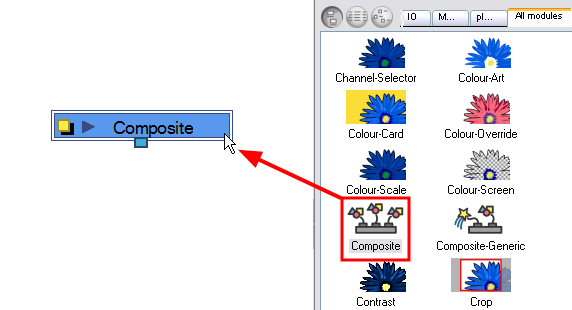
To import modules from the Module Library:
| ‣ | In the Module Library, select a module and drag it to the Network view. |
Composite Module
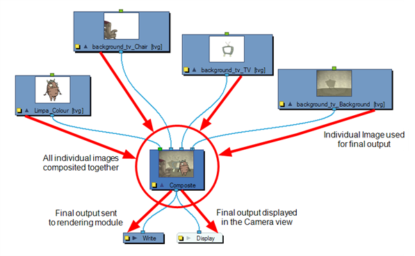
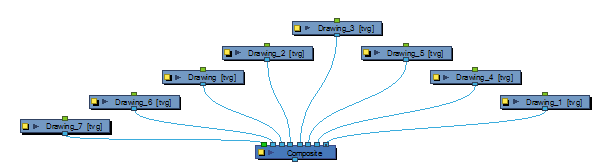
The Composite module allows you to use several images and output a single image. You can compare that to doing pre-compositions in editing software. You connect several drawing modules in your Composite module and one bitmap comes out of it.
By default, the image resulting from the Composite module is a bitmap. The layers are composited together depending on their position on the Z-axis (forward-backward) first, then their order in the Composite module. If two images are at the same position on the Z-axis, their order in the Composite will determine which one is displayed in front and which one is displayed behind.
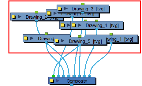
Organizing Modules
When you are working in the Network view and adding many modules, your scene may look a bit messy and be difficult to follow. To fix this, Harmony provides the Order Network script which organizes and displays the modules in a more orderly fashion.
To organize your network:
| 1. | In the Network view, select some or all of your modules. |
| 2. | Display the Scripting toolbar by selecting Window > Toolbars > Scripting. |
| 3. | Click the Order Network Up |
The Order Network Settings dialog box opens.
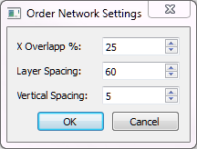
| 4. | Set an X Overlap% value. |
| 5. | Set a Layer Spacing value. |
| 6. | Set a Vertical Spacing value. |
Connecting and Disconnecting Modules
Making or removing connections between modules is quite simple.
To connect modules:
| 1. | In the Network view, do one of the following: |
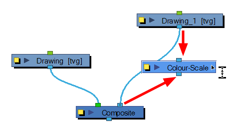
| ‣ | Extend a cable from the first module’s output port and connect it in the second module’s input port. |
| ‣ | Select the module to connect, hold down the [Alt] key and drag the module on an existing cable. |
It is now possible to create links between nodes in the Network views by clicking on one node and ctrl-clicking on a second port. For example:
Select a node and [Ctrl]-click a port:
| • | Click a node and then [Ctrl]-click the in-port of a different node. The nodes are linked. |
| • | Click the out-port of a node and then [Ctrl]-click a different node The nodes are linked. |
| • | Click the out-port of a node, and then [Ctrl]-click a Composite node. The node is linked to a new in-port of the Composite. |
| • | Click a port of a node and then [Ctrl]+[Alt]-click a port of a Composite node. The selected port replaces the link in the Composite's in-port. |
| • | Click an out-port of a node and then [Ctrl]-click the in-port of a Group node. The selected output port replaces the link to the group. |
| • | Click an out-port of a node and then [Ctrl]+[Alt]-click the in-port of a Group node. The selected output port links to a new in-port of the group. |
To disconnect modules:
| 1. | In the Network view, do one of the following: |
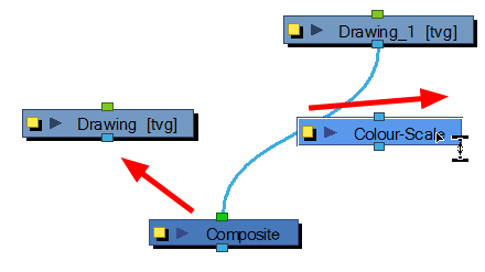
| ‣ | Select the module to disconnect, hold down the [Alt] key and drag the module away. |
Cable Styles
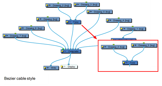
You can customize the look of the cables in the Network view to fit your style of working. You can display the cable lines as Bezier (curved) lines or straight lines.
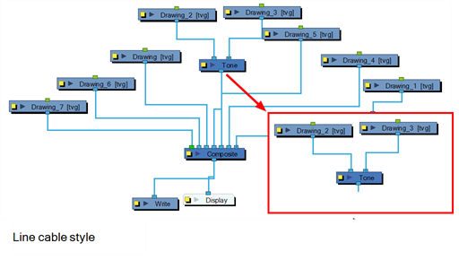
To switch cable styles:
| ‣ | In the Network View menu, select View > Cable Style > Bezier or Line. |
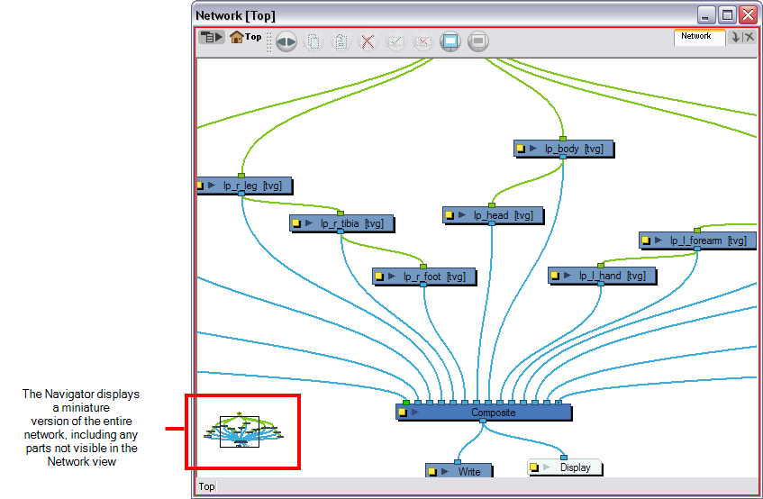
Navigator Display
The Navigator is a small square window inside the Network view that displays a bird's eye view of the network. The view displayed in the Network view is shown framed in the Navigator display. You can drag this frame to pan the current Network view display.
Showing and Hiding the Navigator
You can show or hide the Navigator from the Network view.
To show or hide the navigator, do one of the following:
| ‣ | In the Network View menu, select View > Navigator > Hide Navigator or Show Navigator. |
| ‣ | Press [Ctrl] + [Shift] + [W] (Windows/Linux) or [⌘] + [Shift] + [W] (Mac OS X). |
Positioning the Navigator
The Navigator display can be placed in any corner of the Network view.
To position the navigator:
| ‣ | In the Network View menu, select View > Navigator > and select Top Left, Top Right, Bottom Left, or Bottom Right. |
Magnifying the Network view:
The magnifier helps you view the entire network so you can navigate and view the different modules.
To magnify the Network view:
| 1. | Press [Z]. |
A black outline surrounds the area you were at before pressing [Z].
| 2. | Change the magnification level of the magnifier by rolling the mouse wheel. |
Panning the Network View
Once you have selected a node, you can pan the Network view to navigate around when your network grows more complex.
To pan the Network view:
| 1. | Select a node, press [Spacebar] and drag to a new location. |
Related Topics
| • | Composite Layer Properties |
| • | Grouping Modules |
| • | Enabling and Disabling Modules |
| • | Module Thumbnails |