Lecture Notes
This topic is divided as follows:
| • | Importing Bitmap Images |
| • | Importing and Vectorizing Images |
| • | Importing PSD Files as Separate Layers |
| • | Setting the Camera Frame |
| • | Positioning the Scene Components |
| • | Selecting a Layer |
| • | Positioning an Element using the Transform Tool |
| • | Transform Tool Properties |
| • | Locking Layers in the Timeline View |
| • | Flipping an Element |
| • | Resetting a Transformation |
| • | Cloning and Duplicating Layers |
| • | Setting Up the Network |
| • | Setting Up the Living Room |
Importing Bitmap Images

Images come in many different file formats and are usually saved in a format that retains the original specifications set by the creator of the image. Some formats are able to preserve transparency or transparent layers, while others are not resolution dependent due to their vector nature. Harmony supports the following formats: JPEG, BMP, PNG, TGA, PSD, TIFF, SGI, TVG, OMF, PAL, SCAN, and YUV.
Importing a Bitmap Image without Vectorization
A bitmap image is composed of pixels that is both size and resolution-dependent.
To import a bitmap image:
| 1. | Do one of the following: |
| ‣ | From the top menu, select File > Import > Images. |
| ‣ | In the File toolbar, click the Import Images |
| ‣ | In the Xsheet view, right-click (Windows) or [Ctrl]+click (Mac OS X) anywhere in the frame area and select Import > Images. |
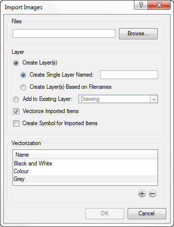
The Import Images dialog box opens.
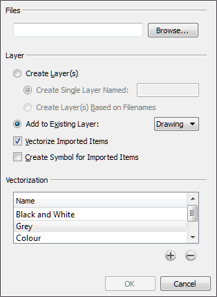
| 2. | In the Files section, click Browse to locate one or more images on your computer. |
| 3. | In the Layer section, you now have the option of creating a new layer for your image or adding the image to an existing layer. Do one of the following: |
| ‣ | To create a new layer, select Create Layer(s) > Create Single Layer Named and name your layer accordingly. |
| ‣ | To create a new layer using the file name, select Create Layer(s) > Create Layer(s) Based on Filenames. |
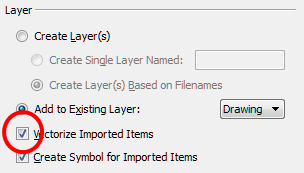
| ‣ | To add the image to an existing layer, select Add to Existing Layer and select the layer already created in your scene. If only vector layers are available in your scene, select the Vectorize Imported Items, Create Symbols for Imported Items or select both options to put your bitmap image on a vector layer. |
| 4. | Deselect the Vectorize Imported Items option. |
The Vectorization options are hidden and the Transparency section appears.
![]()
| 5. | In Harmony, if you want your bitmap images to be encapsulated in a Symbol, select the Create Symbol for Imported Items option. If not, deselect the option. If you chose to add your image to an existing vector layer, then the Create Symbol for Imported Items will automatically be selected and greyed out. |
| 6. | In the Alignment section, decide on the size and placement of your image within the camera frame. Depending on the Scene Settings (the height and width, in pixels, that you chose for your project), an image that you import will be scaled to the point where all its individual pixels become visible. |
The following options are available:
| ‣ | Alignment > Rules > Fit |
If your image orientation is portrait format, this selection will enlarge or shrink (but not distort) to your image’s height to match the full height of the camera frame.
If your image orientation is landscape format, this selection will enlarge or shrink (but not distort) your image’s size so that its width matches that of the camera frame.
| ‣ | Alignment > Rules > Pan |
This selection achieves the opposite result of the Fit command.
If your image orientation is portrait, its width will be made to match the width of the camera frame. As a result, part of the image’s height will extend beyond the height of the frame.
If your image orientation is landscape, the image will extend beyond the width of the camera frame.
This can be useful if you want to make your background move up and down, or from left to right to make it appear as if the camera is panning, or to actually perform a camera pan.
| ‣ | Alignment > Rules > Project Resolution |
This selection will scale the image up or down in proportion to the scene's resolution. It looks at the resolution of the bitmap image, for example 4000 x 2000, then compares it to the scene's resolution, for example 1920 x 1080 and adjusts the scale factor in proportion. So in this example the bitmap would appear at 208% (4000/1920). If you import a bitmap that is 960 x 540 it will be displayed at 50% (960/1920) of the size of the project resolution.
| 7. | The last step is to decide on the image’s Transparency from the Alpha menu. For this, there are four options available. These options deal with the way the bitmap image will be antialiased, more specifically the way that the pixels along the edge are blended in the RGBA (red, green, blue, alpha (transparent) channels. |
![]()
The following options are available:
| ‣ | Premultiplied with White: Individual pixels at the edge of an image are blended with white. |
| ‣ | Premultiplied with Black: Pixels at the edge of an image are blended with black. |
| ‣ | Straight: Pixels at the edge of an image are blended with black, white, and greys. |
| ‣ | Clamp Colour to Alpha: Premultiplies the colour value with the alpha value. When the colour is clamped to the alpha, the colour value cannot be higher than the alpha value. If you have a pixel of value R=247, G=188, B=29 and the alpha is 50% (the image is 50% transparent), then the actual RGB value outputs would be half of the amounts listed above. |
| 8. | Click OK. |
Bitmap Image Quality
If the bitmap images that you have imported look blurry or slightly pixelated, follow the steps below to clean-up the image. These steps effect the quality of the preview in Camera view, but have no effect on the final render.
| 1. | In the Camera view, double-click on the bitmap image to enter its Symbol if the image is encapsulated or simply select the bitmap image layer in the Timeline if it isn’t. |
| 2. | In the top menu, select View > Bitmap Image Quality or press [Ctrl] + [Q]. |
The Bitmap Image Quality dialog box opens.
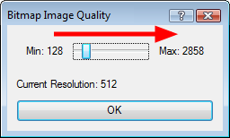
| 3. | Move the Bitmap Image Quality slider to the right to improve the quality. |
| 4. | Click OK. |
| 5. | If you are inside a Symbol, go to the top of the Camera view and click on “Top” to exit the Symbol and return to your scene. |
Importing and Vectorizing Images
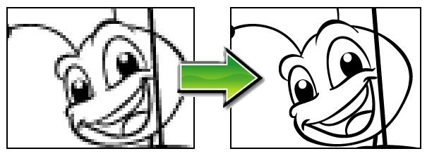
You can turn your images into vector drawings, while maintaining the sketchiness of a pencil line or into vector images with a bitmap fill. Both options can add life to an animation, which straight vectorization with smoothing does not usually afford.
To import and vectorize a bitmap image:
| 1. | In the top menu, select File > Import > Images or click the ImportImage |
The Import Imagesdialog box opens.
| 2. | Click Browse to locate images. |
| 3. | You can create a new layer for your image or add it to an existing layer. |
| ‣ | To create a new layer, select Create Layer(s) > Create Single Layer Named and name your layer accordingly. |
| ‣ | To create a new layer using the file name, select Create Layer(s) > Create Layer(s) Based on Filenames. |
| ‣ | To add the image to an existing layer, select Add to Existing Layer and select the layer already created in your Harmony scene from the drop-down menu. If only vector |
| 4. | In the Layer section, select the Vectorize Imported Items option. |
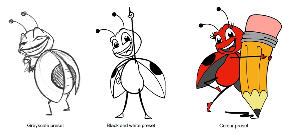
| 5. | In the Vectorization section, decide whether you want to import your image in colour, black and white, or grey. |
| ‣ | Black and White: Vectorizes drawings as a solid black line; creates a 100% vector-based drawing. |
| ‣ | Colour: Vectorizes your image as a colourful bitmap texture within a vector frame. |
| ‣ | Grey: Vectorizes your image as a mix of vector contour and greyscale bitmap filling. Lines keep the texture from the scan, and the white of the paper becomes transparent. |
| ‣ | New Preset: The New Preset |
| ‣ | Delete Preset: The Delete Preset |
You can double-click on any of the presets at any time to open the Vectorization Parameters dialog box to customize your option.
| 6. | Click OK. |
A Symbol or new layer contains the vector drawing. For images contained in a Symbol, double-click on the image’s first cell in the Timeline view to enter the Symbol so you can edit the image.
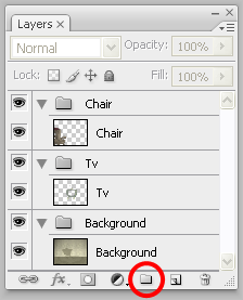
Importing PSD Files as Separate Layers
PSD files (a format exportable exclusively from Adobe Photoshop) are unique in that they are able to retain multiple layers. This is advantageous as the image remains fully editable in terms of any colour correction, effects, masking, transparency, or compositing that were made to the PSD file in Adobe Photoshop.
To import the separated layers of a PSD file:
| 1. | Organize your Adobe Photoshop file so that all your layers are “grouped” into individual folders, or that all the elements you want to import as a single layer in Harmony are grouped together in their own folder. Any layer that is not in a folder group, by itself or otherwise, will not be imported. |
| 2. | In Harmony, go to the top menu and select File > Import > Images or click the Import Image |
The Import Drawings dialog box opens.
| 3. | Click Browse to find and select the PSD image on your computer. |
| 4. | Select the Create Layer(s) option. |
| 5. | Select the Create Single Layer Named or Create Layer(s) Based on Filenames option. |
| 6. | Decide whether to select Vectorize Imported Items option. |
| 7. | Decide whether to select the Create Symbol for Imported Items option. |
| 8. | Click OK. |
The Multilayer Image Import Settings dialog box opens.
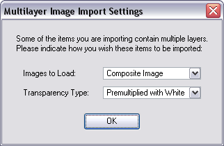
| 9. | In the Image to Load menu, select: |
| ‣ | Composite Image to flatten your layers. |
| ‣ | All Layers Image to keep your layers separated. |
| 10. | Select the Transparency Type if applicable. To learn more about the different Transparency Type options, see Importing a Bitmap Image without Vectorization . |
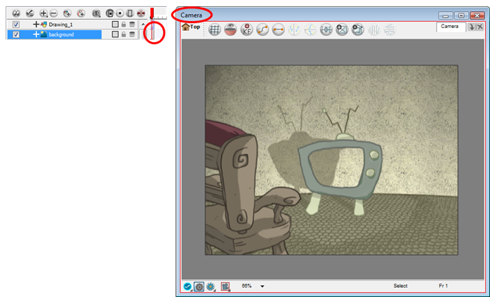
Your image should appear as separate layers in the Timeline view, corresponding to the PSD layer group folders.
Setting the Camera Frame
The scene action occurs inside the camera frame, so it’s really important to set it up correctly.
The Camera layer is static which means that if you need to animate it, you must add a peg which you will learn about later on.
Adding a Camera Layer
To set the camera frame, you need to add a Camera layer to your scene so you can edit the default camera frame.
To add a Camera layer in the Timeline view, do one of the following:
| ‣ | In the Timeline view, click the Add Layer |
| ‣ | From the top menu, select Insert > Camera. |
A new camera layer is added to your scene and appears in the Timeline view.
Positioning the Scene Components
Setting up the scene also involves positioning the different scene elements within the camera frame.
Animate Mode
When positioning elements, make sure that the Animate Mode is turned off, or it will create a keyframe within the drawing layer.
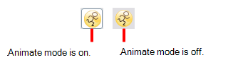
To turn off the Animate mode:
| ‣ | In the Tools toolbar, click the Animate Mode |
Selecting a Layer
There are different ways of selecting the layers you want to reposition in the Camera view.
Selecting a Layer from the Camera View Using the Transform Tool
You can select your elements directly in the Camera view using the Transform tool. When you select the Transform tool, its properties and options appear in the Tool Properties view.
When using the Transform tool to select elements in the Camera view, always make sure that the Peg Selection Mode option in the Transform Tool Properties view is disabled or else it will limit the selection to peg only.
To select from the Camera view:
| 1. | In the Tools toolbar, select the Transform |
| 2. | In the Transform Tool Properties view, make sure that the Peg Selection Mode |
| 3. | In the Camera view, select the element to be repositioned. You can select more than one element at a time. |
The corresponding layers and columns are highlighted in the Timeline and Xsheet views.
Positioning an Element using the Transform Tool
Using the Transform tool, you can easily reposition, scale, rotate and even skew layers directly in the Camera view.
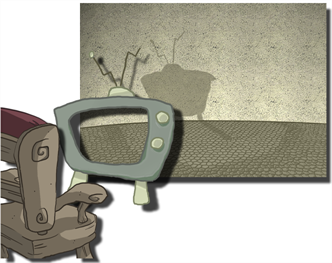
Panning a Drawing Layer
![]()
To pan a layer using the Transform tool:
| 1. | In the Tools toolbar, select the Transform |
| 2. | In the Transform tool Tool Properties view, make sure the Peg Selection Mode |
| 3. | In the Camera view, select a drawing layer and drag the selection to a new area. You can select multiple layers to reposition them at once. |
Rotating a drawing layer
![]()
To rotate a layer using the Transform tool:
| 1. | In the Tools toolbar, select the Transform |
| 2. | In the Transform tool Tool Properties view, make sure the Peg Selection Mode |
| 3. | In the Camera view, select a drawing layer and rotate the transform bonding box handle. |
A preference in the Camera tab will add a rotation handle to your object’s bounding box.This preference is off by default.
Scaling an Element
![]()
To scale a layer using the Transform tool:
| 1. | In the Tools toolbar, select the Transform |
| 2. | In the Transform tool Tool Properties view, make sure the Peg Selection Mode |
| 3. | In the Camera view, select a drawing layer and pull or push on the size, top, or corner control point. Hold down [Shift] to lock the selection’s ratio. |
Skewing an Element
![]()
To skew a layer using the Transform tool:
| 1. | In the Tools toolbar, select the Transform |
| 2. | In the Transform tool Tool Properties view, make sure the Peg Selection Mode |
| 3. | In the Camera view, select a drawing layer and drag sideway or up and down the sides or top and bottom segments, between the control points. |
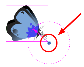
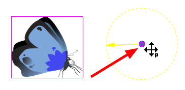
Temporarily Repositioning the Pivot Point
Some transformations are made relative to the pivot point position, such as rotation, scale, skew, and flip. You can use the Transform tool to temporarily reposition this pivot point for each transformation.
To temporarily reposition the pivot point:
| 1. | In the Tools toolbar, select the Transform |
| 2. | In the Transform tool Tool Properties view, make sure the Peg Selection Mode |
| 3. | In the Camera view, select an element. |
The pivot point appears in the Camera view.
| 4. | Drag the pivot point to a new position. |
This is the new position of the pivot point for the current transformation. It will remain in this new position as long as you do not deselect the drawing.
When you translate the pivot using the Transform tool, the permanent pivot appears as a ghost indicating its location and from where the animation will be interpolated when you create motion paths. The animation is always interpolated from the original pivot, not the temporary pivot.
Transform Tool Properties
![]()
|
Tool |
Description |
|
|
|
Select and Transform |
Switches between the Select and Transform tools directly from the Transform or Select Tool Properties views. |
|
|
Lasso and Marquee |
Lets you choose between the Lasso and Marquee modes to change the selection style of the Transform tool. Click and hold [Alt] to temporarily switch from the currently selected mode to the other. |
|
|
Peg Selection |
Limits the selection in the Camera view to pegs. When deselected, the Transform tool selects the drawing layers. |
|
|
Flip Horizontal, Flip Vertical |
Flips the selection horizontally or vertically. Animation > Flip > Flip Horizontal or Flip Vertical Press [4] or [5]. |
|
|
Rotate 90 CC, Rotate CCW | Rotates the selection 90 degrees clockwise or counter-clockwise. |
|
|
Width, Height |
Lets you enter specific values to resize the selected layer. Click the Lock icon to lock/unlock the ratio between the width and height values. |
|
|
Angle |
Lets you enter specific values, in degrees, to rotate the selected layer. |
|
|
Offset X and Y |
Lets you enter specific values to reposition the selected layer. |
|
|
Snap and Align |
Snaps the selected layer to any existing line, while automatically displaying temporary rulers that guide you, which you can also snap your object to. |
|
|
Snap to Grid |
Snaps your selection according to the grid. |
Locking Layers in the Timeline View
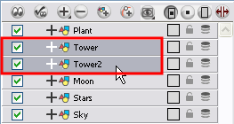
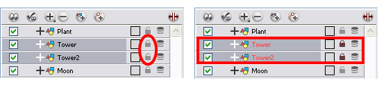
You can prevent correctly positioned layers from being selected by locking them in the Timeline view. This is useful for making a multiple selection inside the Camera view and leaving them visible. Once a layer has been locked, its locked state will be remembered next time you open your saved project.
To lock a layer or a selection of layers:
| 1. | In the Timeline view, select one or more layers. |
| 2. | Do one of the following: |
| ‣ | From the top menu, select Animation > Lock > Lock. |
| ‣ | Click one of the selected layer’s Lock |
| ‣ | Press [Ctrl] + [Alt] + [L] (Windows/Linux) or [⌘] + [Alt] + [L] (Mac OS X). |
All selected layers are locked.
Permanently Repositioning the Pivot Point
Some transformations, such as the rotation, scale, skew and flip, are made relative to the pivot point position. You can reposition this pivot point anywhere using the advanced animation tools.
To permanently reposition the pivot point:
| 1. | In the Advanced Animation toolbar, select the Rotate |
| 2. | In the Camera view, [Ctrl] + click (Windows/Linux) or [⌘] + click (Mac OS X) to select your element. |
The pivot point appears in the Camera view.
| 3. | Drag the pivot point to a new position. |
This is the new position of the pivot point for future transformations until you reposition it.
Flipping an Element
There are two different options you can use when you want to flip your element.
Flip Horizontal and Flip Vertical
The Flip Horizontal and Flip Vertical options let you flip a drawing layer along the Camera view’s horizontal and vertical axis.
To flip a layer:
| 1. | In the Tools toolbar, select the Transform |
| 2. | In the Transform Tool Properties view, make sure that the Peg Selection Mode |
| 3. | In the Camera view, use the Transform |
| 4. | Select Animation > Flip > Flip Horizontal or Flip Vertical or press [4] or [5]. |
Flip Scale X and Flip Scale Y
Once your drawing layer is rotated, the original horizontal and vertical axes change. The Flip Scale X and Flip Scale Y will perform a flip on your drawing layer following its original axis.
| • | The Flip Horizontal command flips the Layer following the Camera view X-axis. |
| • | The Flip Scale X command remembers the original X-axis of the layer and flips the element following it. |
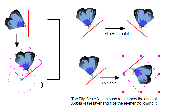
To flip an element following its original axis:
| 1. | In the Transform Tool Properties view, make sure that the Peg Selection Mode |
| 2. | In the Camera view, use the Transform |
| 3. | Select Animation > Flip > Flip Scale X or Flip Scale Y. |
Resetting a Transformation
You can easily reset layers to their original position in the Camera view. Use the Select command to reset the value of the selected element to the initial value of the active tool. For example, if the Rotate ![]() tool is active, the transformation angle will be reset to 0 and if the Transform
tool is active, the transformation angle will be reset to 0 and if the Transform ![]() tool is active, the entire transformation values will be reset.
tool is active, the entire transformation values will be reset.
To reset the layers` position:
| 1. | In the Tools toolbar, select the Transform |
| 2. | In the Timeline or Camera view, select one or more drawing layers to reset. |
| 3. | Do one of the following: |
| ‣ | From the top menu, select Animation > Reset or press [R]. |
| ‣ | Right-click the selected layers and select Clear All Values. |
| ‣ | In the Timeline view, select Layers > Clear All Values from the Timeline View menu. |
The selected layers return to their original position.
Cloning and Duplicating Layers
You may need to clone or duplicate a layer during a production. This allows you to modify the layers drawings or the timing independently from the original column.
Cloning Layers
A cloned layer is linked to the original element directory. If a drawing is modified in the original or cloned layer, both will be updated. However, clone layers can have different timings.
For example, if you make a walk-cycle for a soldier and want to use it for a whole army, you may want to have fifty layers with fifty different drawing exposures to produce a slight difference in the timing. You don’t necessarily want the same drawing fifty times. If you copy your layers and their drawings fifty times over, it will create a very heavy scene. It is better to clone the fifty layers from the same initial layer to have them all linked to the same walk cycle drawings, producing fifty layers but one drawing directory. This will also allow you to correct the drawings in one layer and have all of the other ones updated simultaneously.
To clone a layer:
| 1. | In the Timeline view, select a layer to clone. |
| ‣ | In the Network view, select the module you want to clone. |
| 2. | In the Timeline View menu, select Layers > Clone Selected Layers. |
| ‣ | In the Network View menu, select Modules > Clone Selected Modules. |
Note that the module appears in the Timeline view if it is not connected to the Composite module or if the Display mode is not set on Display All.
Duplicating Layers
You can duplicate a layer to have a copy of the drawings that are independent from the original column, as well as an independent timing (exposure). When you need the drawings to be modified independently, you will want to duplicate the layer instead of cloning it.
To duplicate a layer:
| 1. | In the Timeline view, select the layer to duplicate. |
| ‣ | In the Network view, select the module you want to duplicate. |
| 2. | In the Timeline View menu, select Layers > Duplicate Selected Layers. |
| ‣ | In the Network View menu, select Modules > Duplicate Selected Modules. When you duplicate a module, it does not automatically connect itself to the Composite module of your scene. |
The duplicated layer appears.
By default when you select a module in the Network view and do a copy paste using [Ctrl] + [C] and [Ctrl] + [V] (Windows/Linux) or [⌘] + [C] and [⌘] + [V] (Mac OS X), this creates a CLONE not a duplicate. Modules will be linked to the same drawings. Pegs will be linked to the same function columns.
To duplicate a layer in the Network view using shortcuts, you must do [Ctrl] + [C] (Windows/Linux) or [⌘] + [C] (Mac OS X) and [Ctrl] + [B] (Windows/Linux) or [⌘] + [B] (Mac OS X) for Paste Special, and selecte Create New Columns.
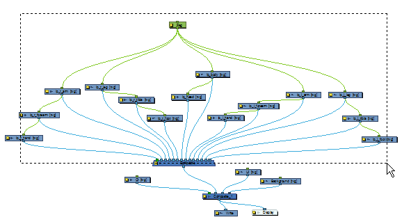
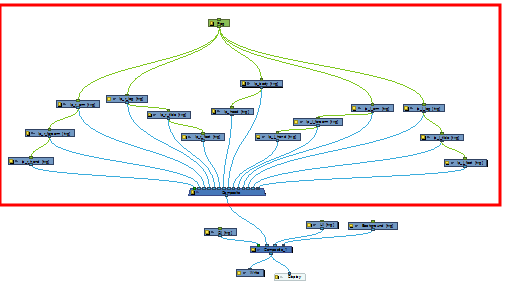
Setting Up the Network
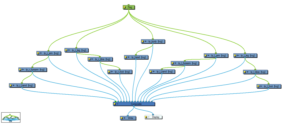
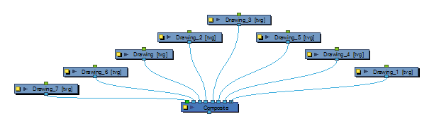
The Network view uses a visual set of connections to show how each element in the scene is brought to the final image. It allows you to add extra elements and effects, and to move beyond the possibilities offered by the Timeline and Xsheet views.
Network Navigation and Basic Rules
The basic rules of the Network view are quite simple. Once you understand them, a lot can be accomplished.
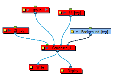
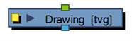
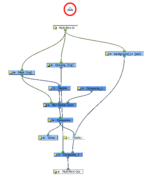
Each element in the Network view is called a module. There are several different types of modules:
|
Module |
Description |
|
| Drawing |
|
Transfers drawing information. |
| Effect |
|
Processes effects on drawings and transfers drawing information. |
| Input/Output |
|
Act as the interface between each module and network. |
| Move |

|
Controls the camera and element transformations over time. |
| Compositing |
|
Combines multiple source images. |
About Input and Output Ports
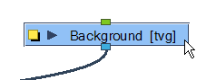
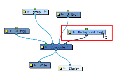
Each module has an input port at the top and an output port at the bottom. Some are blue and others are light-green or bright green.
| • | Blue indicates drawing information. |
| • | Light Green indicates position and movement. |

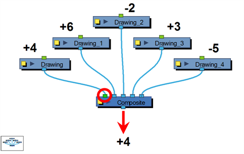
| • | Bright green shows the element on top of the composition and outputs that element’s Z position to the Composite module. When many elements have different Z positions (multiplane, different distances from the camera) and are placed through a Composite module that flattens them together (producing one image with one Z value), the system needs to give a Z position to this new image. It uses the bright green port information. |
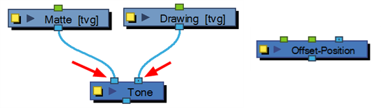
Finally, some modules contain more than one Input port. These are usually Effects modules needing different drawing or position information in order to perform their calculation. When the two ports are blue, the Drawing is on the right and the Matte is on the left. If it is light green, the drawing needs extra position information.
Adding Modules
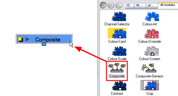
Each module used to build a network is available in the Module Library view. In addition, each time you create a layer from the Timeline or Xsheet views, the corresponding module is created in the Network view.
To import modules from the Module Library:
| ‣ | In the Module Library, select a module and drag it to the Network view. |
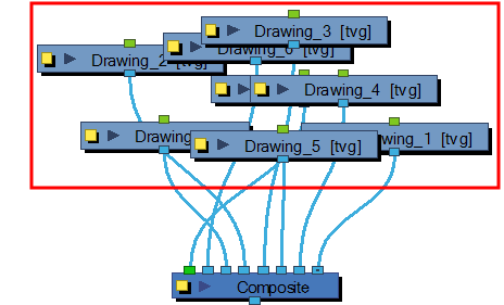
Organizing Modules
When you are working in the Network view and adding many modules, your scene may look a bit messy and be difficult to follow. To fix this, Harmony provides the Order Network script which organizes and displays the modules in a more orderly fashion.
To organize your network:
| 1. | In the Network view, select some or all of your modules. |
| 2. | Display the Scripting toolbar by selecting Window > Toolbars > Scripting. |
| 3. | Click the Order Network Up |
The Order Network Settings dialog box opens.
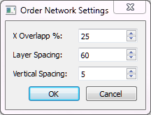
| 4. | Set an X Overlap% value. |
| 5. | Set a Layer Spacing value. |
| 6. | Set a Vertical Spacing value. |
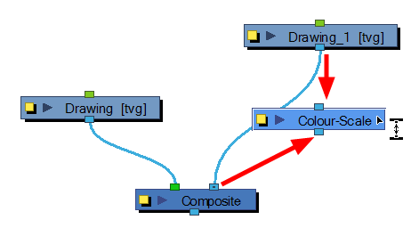
Connecting and Disconnecting Modules
Making or removing connections between modules is quite simple.
To connect modules:
| 1. | In the Network view, do one of the following: |
| ‣ | Extend a cable from the first module’s output port and connect it in the second module’s input port. |
| ‣ | Select the module to connect, hold down the [Alt] key and drag the module on an existing cable. |
It is now possible to create links between nodes in the Network views by clicking on one node and ctrl-clicking on a second port. For example:
Select a node and [Ctrl]-click a port:
| • | Click a node and then [Ctrl]-click the in-port of a different node. The nodes are linked. |
| • | Click the out-port of a node and then [Ctrl]-click a different node The nodes are linked. |
| • | Click the out-port of a node, and then [Ctrl]-click a Composite node. The node is linked to a new in-port of the Composite. |
| • | Click a port of a node and then [Ctrl]+[Alt]-click a port of a Composite node. The selected port replaces the link in the Composite's in-port. |
| • | Click an out-port of a node and then [Ctrl]-click the in-port of a Group node. The selected output port replaces the link to the group. |
| • | Click an out-port of a node and then [Ctrl]+[Alt]-click the in-port of a Group node. The selected output port links to a new in-port of the group. |
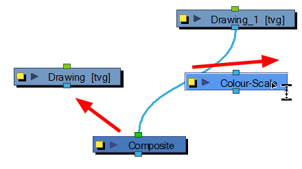
To disconnect modules:
| 1. | In the Network view, do one of the following: |
| ‣ | Select the module to disconnect, hold down the [Alt] key and drag the module away. |
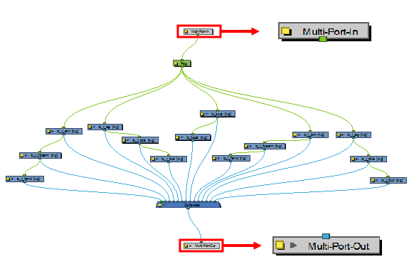
Grouping Modules
With so many connections and modules possible, the network can quickly become crowded. Keep things organized by grouping your modules.
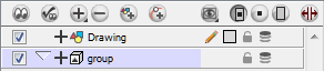
When you select part of a group, this indicated in the Timeline view by a light-blue colour on the affected layer.
Grouping a Selection
To group selected modules:
| 1. | In the Network view, drag a selection around the modules you want to group. |
| 2. | In the Network View menu, do one of the following: |
| ‣ | Select Edit > Group > Group Selected Layers |
| ‣ | Press [Ctrl] + [G] (Windows/Linux) or [⌘] + [G] (Mac OS X). |
The modules are grouped.
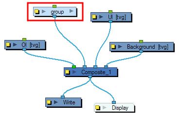
To ensure that you have a Multi-Port Out Module in your group and that your group remains connected, include a Composite module in your selection and make sure it is connected to the main Composite module of the scene before grouping.
Ungrouping a Selection
To ungroup a group:
| 1. | In the Network view, select the group of modules you want to ungroup. |
| 2. | In the Network View menu, select Edit > Group > Ungroup |
The selected group is ungrouped.
Entering and Exiting a Group Module
Once you create a group module, it is easy to enter into or exit from it.
To enter a group module:
| • | In the Network view, click the arrow on the right side of the group module you want to enter. |
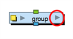
To exit a group module:
| 1. | In the Network view, click the destination in the Group Hierarchy menu. You can also select Modules > Exit Group from the Network View menu or press [Backspace]. |
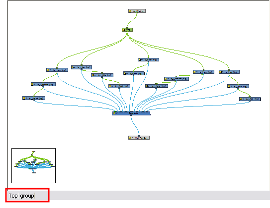
| ‣ | When you enter a group, the Group Hierarchy Menu displays the path to where you are. In this example, we are inside the group named group. To exit this group, click on Top Group. |
To move up a level in a group:
| 1. | Click the arrow at the top of the Network view. |
Enabling and Disabling Modules
As with the Timeline layers, you can turn the Network view modules on or off. When you turn off a module in the Network view, its corresponding layer in the Timeline view is also turned off. Modules that are turned off are displayed in red.
To enable modules:
| 1. | In the Network view, select the disabled module(s) you want to enable. |
| 2. | In the Network View menu, select Modules > Enable or press [A]. This keyboard shortcut is also valid in the Timeline view. |
To enable all modules:
| 1. | In the Network View menu, select Modules > Enable All. |
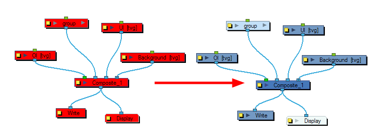
To disable modules:
| 1. | In the Network view, select the module(s) you want to enable. |
| 2. | In the Network View menu, select Modules > Disable or press [D]. |
To disable all other modules:
| 1. | In the Network view, select the module(s) to remain enabled. |
| 2. | In the Network View menu, select Modules > Disable All Others. |
All modules are disabled except for those selected. This operation only affects the current level layers. It does not affect the nested modules within a group.