


Chapter 19: How to Create a Multiplane
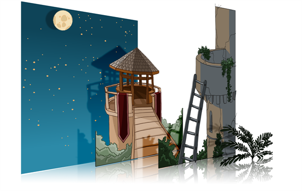
To construct a multiplane, you must imagine what a real environment is like. Take a look at your background picture and imagine a camera moving through the space. Notice that objects in the picture move at different speeds depending on where they are in relation to the camera lens.
Building a multiplane requires an understanding of the scene's background, as well as the positioning of the elements on different layers.
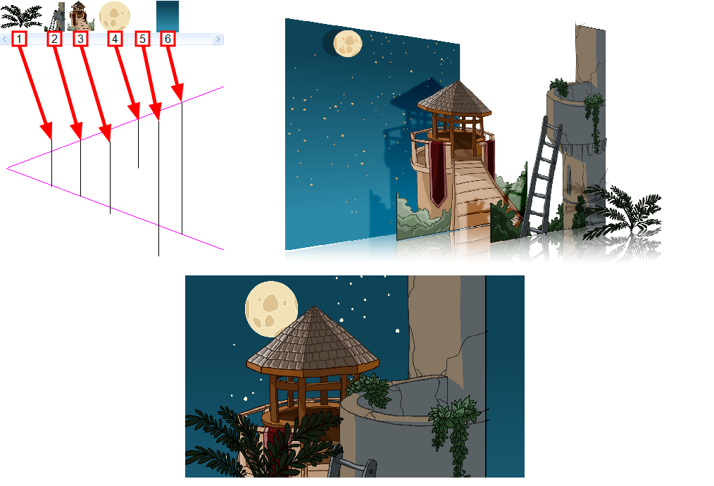
For example, in the background illustrated above, the main objects to be separated are:
- Fern
- Front tower
- Second tower
- Moon
- Stars
- Sky
Although the bottom of the tower is hidden behind the plant and the ladder, each of the multiplane layers should be a complete drawing. This is because hidden portions may show up during a camera move later on in the scene.
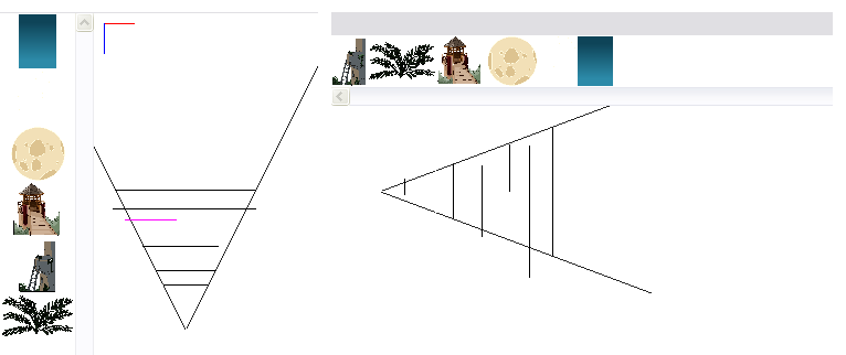
You can position layers on the Z-axis using the Side and Top view.
Positioning your element closer to the camera makes them appear bigger. You can also move elements towards the camera or away from the camera while keeping the same size aspect ratio in the Camera view.
It is a good idea to keep a Camera view open to see what your scene looks like while positioning elements in the Top and Side views
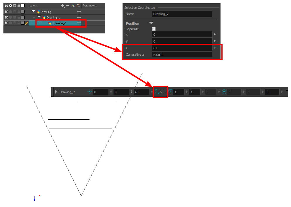
You can see the cumulative Z value information in the Coordinates and Control Points view. When you select a drawing cell that includes a keyframe, it will display the cumulative Z value.
When a layer is parented to other layers that are moved forward or backward on the Z-axis, the currently selected layer's position Z value may not be accurate since its parent will also have an offset on the Z-axis. The Cumulative Z value is a compilation of all the Z-axis offsets to give the real Z-axis offset value related to the (0,0) centre.
- To maintain the visual scale in the Camera view as you move your element, do one of the following:
| ‣ | In the Advanced Animation toolbar, select the Maintain Size |
| ‣ | From the top menu, select Animation > Tools > Maintain Size. |
| ‣ | Press Alt + 6. |
- In the Side or Top view, select one of the layers in the thumbnails section. You can also select a layer from the Timeline view.
The selected layer is highlighted in the Top, Side and Camera views.
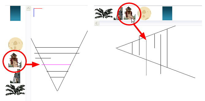
- Drag the layer to the correct depth position in the camera cone. Your element aspect will remain the same in the Camera view.
- For your element to scale up or down in relation to their distance to the camera, do one of the following:
| ‣ | In the Tools toolbar, select the Transform |
| ‣ | In the Advanced Animation toolbar, select the Transl |
| ‣ | Select a layer from the Timeline view. |
The selected layer is highlighted in the camera cone.
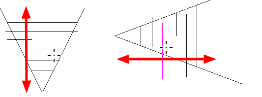
- In the Top view, drag the element sideways to position it horizontally. Hold Shift while dragging the element to make sure it only moves along the X-axis.
- In the Side view, drag the selected element up or down to position it vertically. Hold Shift while dragging the element to make sure it only moves along the Y-axis.