


Positioning an Element Using the Layer Properties View
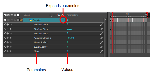
Each layer has a series of parameters that you can modify to adjust an element's position. You can access these parameters in the Layer Properties view. In this view, you can type in a value instead of moving the object in the Camera view. These values can also be animated over time. See Drawing Layer Properties Reference for additional details.
You can also access a layer's parameters in the Timeline view. Click on the Expand Parameters ![]() button.
button.
It is important to understand the coordinate values in Harmony. Harmony's core is based on the origins of animation. In traditional animation, a scene's size and camera motion are calculated in fields. A field has a 4:3 ratio and measures 0.5 inches (12.7 mm) in width. A specific grid has been created for this purpose known as a field chart. Harmony uses this unit of measurement as its coordinate system.
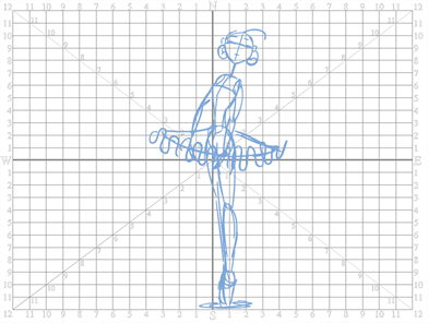
A field chart uses the cardinal directions. The X axis is the east-west (left-right) direction, the Y axis is the north-south (up-down) direction and the Z axis is the forward-backward direction.
In Harmony, a drawing's pivot is located at the centre of the field chart, regardless where your drawing has been drawn on the page. Your drawing is the entire sheet of paper, not only the drawing strokes you have drawn on the page. This allows scanned drawings, imported images and paperless drawings to be properly registered together.
If you want to move your drawing in the upper-left region of the camera frame, you would type in something like the following:
| • | X Axis: -4 or 4W (4 West) |
| • | Y Axis: 5 or 5N (5 North) |
If you want to move your drawing in the lower-right region of the camera frame, you would type in something like the following:
| • | X Axis: 3 or 3E (3 East) |
| • | Y Axis: -2 or 2S (2 South) |
- Do one of the following:
| ‣ | In the Layer Properties view is not part of your workspace, from the top menu, select Windows > Layer Properties. In the Timeline view, select a layer |
| ‣ | In the Timeline view, double-click on a layer. |
| ‣ | Press Shift + E. |
| ‣ | In the Node view, click on a node’s yellow properties button. |
The properties display.
![]()
- In the Timeline view, select a layer.
- In the Layer Properties view, select Enable 3D option to display the 3D parameters in the Layer Properties—see Enabling the 3D Option.
- In the Position section, select one of the following options:
| ‣ | Separate to independently edit the different coordinate fields. Continue to step 3. |
| ‣ | 3D Path to use a 3D path function when animating your element. Continue to step 4. |
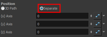
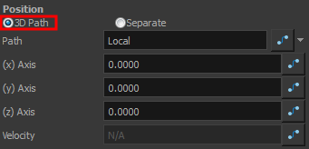
- In the (x), (y) and (z) Axis fields, type in a new coordinates corresponding to the desired position—see Creating a Multiplane.
As you type in values, the element’s position is updated in the Camera view.
| 1. | Use the Function |
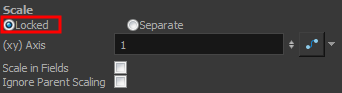
- In the Scale section, select one of the following options:
| ‣ | Locked to resizes the element uniformly in three directions. |
| ‣ | Separate to resize the element in any direction without affecting the others. |
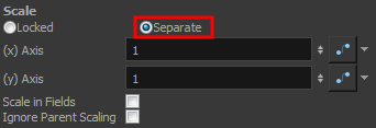
- In the (x) and (y) Axis fields, type in a new coordinates corresponding to the desired position
| 2. | Use the Function |
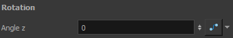
- In the Rotation section, Angle z field, type in a degree value for the rotation angle. Note that you can enter values greater than 360 and -360 degrees. If you enter 720, the object will rotate twice.
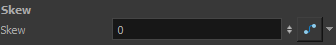
- In the Skew field, type in a degree value between -90 to 90 for the skew angle.
- In the Pivot section, type in the desired coordinate value to reposition the transformation pivot. This will change the permanent position of the pivot.
For detailed information on the Layer Properties parameters, see Drawing Layer Properties Reference.