


Image Fracture
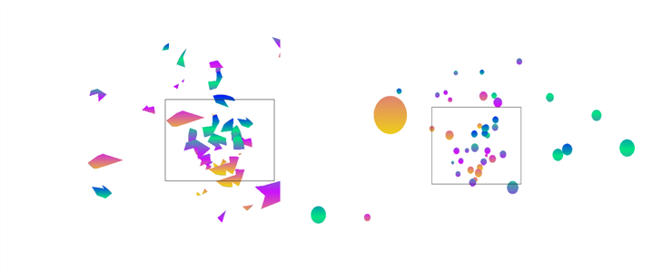
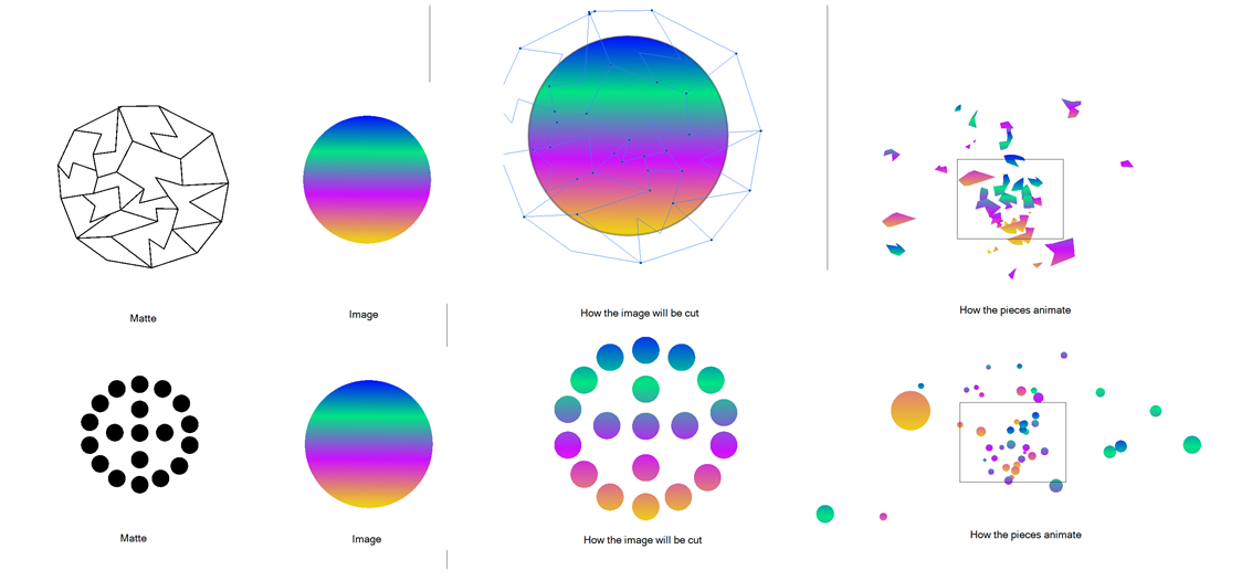
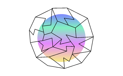
The Image Fracture effect lets you break an image into pieces. This effect requires two image objects: the image to be cut and the shape of the cut pieces (matte). The image to be cut can be anything from a vector drawing to a bitmap image to an entire scene's composite, with effects and all. The image to be cut should be hooked to the Image Fracture's first port.
The matte should be a flattened if you want it to work like a cookie cutter (hollow shape with a frame) and can be composed of either brush or pencil lines. It can also be a solid shape, many solid filled shapes and even many solid filled overlapping shapes. When the matte is made of overlapping pieces, the cut image will be multiplied at those zones to break apart in multiple layers. The matte drawing should be hooked to the Image Fracture's left port.
The two image objects overlap perfectly when combined in the Image Fracture. This means that you have to take the 12 by 12 field into account when judging the scale and proportion of these objects. If the matte does not overlap a part of the image, that part of the image will not be cut. The matte does not have to be a continuous shape. It could be three separate circles, which would then be cut and pulled away from the image.
Here is an example of a network with the Image Fracture effect:
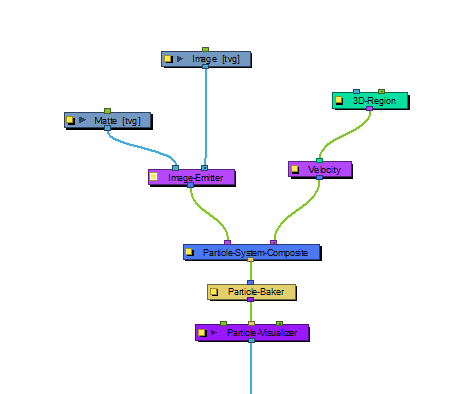
Image Fracture Properties
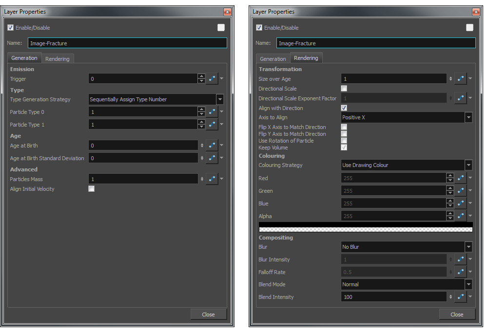
Generation Tab
| Parameter | Description |
| Emission | |
| Trigger |
An on/off switch using binary code. 1 = on, 0 = off. |
| Type |
You may want to design a variety of different drawings that will vary the appearance of your particle system. In this case, you should put each drawing on its own cell in the drawing layer. Each drawing will then be a new Type of particle. |
| Type Generation Strategy |
Lets you choose sequentially assign a type (moving from one drawing to the next) or randomly. |
| Particle Type 0 |
This is the frame number where the first drawing can be found. If you have a 5-frame cycle that starts on frame 1, you would put a 1 here. |
| Particle Type 1 |
This is the frame number where the last drawing can be found. If you have a 5-frame cycle that starts on frame 1, you would put 5 here. |
| Age | |
| Age at Birth |
A different start frame number can be entered in this field. This means that a particle can start with a different drawing than the drawing on frame 1. |
| Age at Birth Standard Deviation |
Allows a random deviation for the birth of the particles. If you have a five-frame cycle that starts on frame 1, but you want the particles to be a random type, then you may want to set the Age and Birth to 3 with a standard deviation of 2. That means the particles will randomly be born at any frame from 1 to 5. |
| Advanced | |
| Particles Mass |
Define a mass for the particles which will affect how the particles interact with gravity. |
| Align Initial Velocity |
Aligns the initial velocity with the region from which the particles are being emitted. If you are emitting from a sphere, then the particles will all start out moving away from the centre of the sphere. |
Rendering Tab
| Parameter | Description |
| Transformation | |
| Size over Age |
Lets you set how you would like the size of the particle to change as it ages. Attach a function to this attribute if you would like to, for example, have the particles get smaller as time goes on. |
| Directional Scale |
Scales the particle in the direction of its movement. |
| Directional Scale Exponent Factor |
Set an exponent here for how much you would like that particle to scale. |
| Align with Direction |
Aligns the particle in the direction of its movement. |
| Axis to Align |
Select the axis that you want to align. This axis refers to the axis of the Drawing grid from the Drawing module plugged into the emitter. |
| Flip X Axis to Match Direction |
You might want to have the particle align to the X direction of movement. You can see this property being used in the Lemmings example. |
| Flip Y Axis to Match Direction |
Similar to flipping the X axis, you may wish to flip the Y axis of a drawing to match the direction of the particle movement. |
| Use Rotation of Particle |
Enables rotation on the particle. |
| Keep Volume |
When you choose to do a Directional Scale, this will automatically maintain the volume of the particle by squashing it proportionally to how much it stretches as a result of the directional scale. |
|
Colouring |
|
| Colouring Strategy |
Lets you choose how to define the colour of the particle. |
| Use Drawing Colour |
In this case, the particle will remain the same colour as it was drawn with. |
| Map RGB Based on Age |
Attach a function to this to vary the Red, Green, and Blue values of the particle as it ages. |
| Map RGBA Based on Age |
Attach a function to this to vary the Red, Green, Blue, and Alpha values of the particle as it ages. |
| Apply Opacity Based on Age |
Keep the original RGB values from the drawing, but vary the Alpha (Opacity) according to a function that you define here. |
| Map RGB Based on Frame |
Change the Red, Green, and Blue values of the particles based on the frame. Changing based on the frame means that ALL particles will change colour on that frame, regardless of their age. |
| Map RGBA Based on Frame |
Change the Red, Green, Blue, and Alpha values of all particles on a given frame by attaching a function. |
| Apply Opacity Based on Frame |
Use the original RGB values from your drawing, but vary the Alpha (Opacity) of the particles on a certain frame by attaching a function to this. |
| Red, Blue, Green, Alpha |
This is where you can attach functions to the Red, Blue, Green and Alpha values. You can also click on the colour swatch to adjust the colour. |
| Compositing | |
| Blur |
Lets you attach a function to define how you want the particles to blur based on the age, frame or camera distance of each particle. There are low and high quality blurs. Also, you can attach a function to define how all particles should be blurred. |
| Blur Intensity |
Lets you set a value or attach a function to animate the blur according to the type of blur that was defined from the drop-down list. |
| Falloff Rate |
The distance where the blur fades from the edge of the image. Select a value between 0 and 1. A falloff rate of 0 causes the blur to fade out slowly, distributing the blur evenly from the edge of the drawing to the farthest edge of the blur. A falloff rate of 1 causes the blur to fade out quickly so that the blur is heaviest at the edge of the drawing. |
| Blend Mode |
Defines a blend mode for the particles to get cool effects. |
| Blend Intensity |
This is a percentage of how opaque you want the particles to be blended. A value of 50 = 50% transparent. A value of 100 = fully opaque. |