Differences between Pegs and Animated Layers
There are two ways to create motion paths: animated drawing layers and pegs. They each have different purposes.
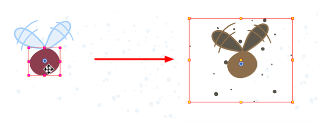
You can create a motion path directly on layers (animated layers).
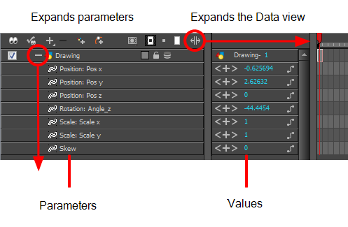
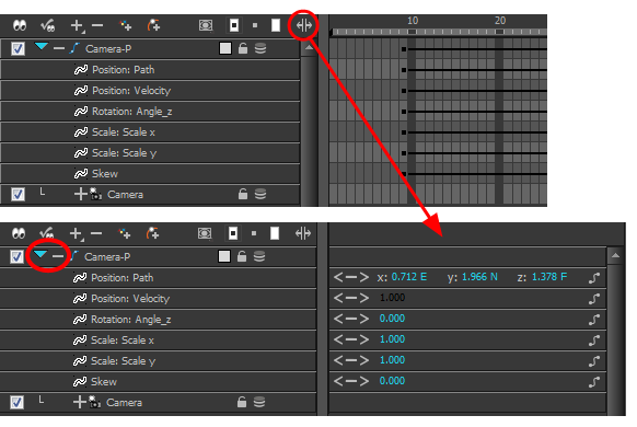
You can control and define a trajectory using several different parameters, including:
| • | X, Y and Z positions (3D Path or Separate Positions) |
| • | Angle (rotation) |
| • | Skew |
| • | X and Y Scales |
| • | Euler Angle or Quaternion Angle (when 3D option is enabled) |
| • | Z Scale (when 3D option is enabled) |
Each parameter has its own function curve where you can add keyframes and control the easing.
If you are not familiar with graphs and function curves, Harmony has a series of easy-to-use tools for visually controlling trajectories in the Camera and Timeline view.

By default, a drawing layer can be animated using the same parameters as a peg, but you can disable this feature. Being able to switch your drawing layers so they can no longer be animated without a peg has certain advantages. In cut-out animation, it is easier to separate drawing exposure and keyframes to change the timing easier and rearrange keyframe position in the Timeline view. This also works for backward compatibility when bringing in templates created in older versions of the software, so as not to lose their offset keyframes or drawing substitution keyframes.
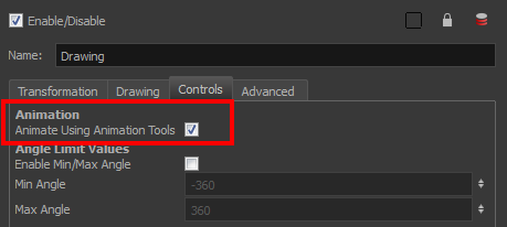
If you do not want to animate a drawing layer, you have the option of disabling its animation parameter. To do so, simply select the layer and in the Layer Properties view, deselect the Animate Using Animation Tools option on the Controls tab.
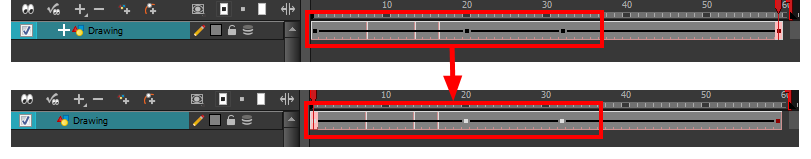
If your layer was already animated and you deselect the Animate Using Animation Tools option, your keyframes will be dimmed, enabling you to easily identify them as ones that cannot be modified. Select the Animate Using Animation Tools option in order to modify them again.
A Peg layer is a trajectory that contains no drawings on which you can hook your drawings.
Pegs have been used for a long time in the traditional animation process, mainly for registration purposes. Peg holes at the bottom or top of the animation paper are used to keep all the sheets even and at the same registration.
There are three peg holes in regular animation paper. The centre peg hole is round while the left and right ones are oval shaped. The oval peg holes are located on each side of the page, four inches away from the centre peg hole.
To keep the drawings together, the animator uses a peg bar. This peg bar has three pins that correspond to the shape and location of the peg holes. Peg bars are normally found at the bottom and top of animation discs.
Before digital compositing, the peg bars were also used to move layers on the camera stand to create pans and camera moves. They were the equivalent of digital trajectories. Harmony makes use of these concepts to create animation and camera motion.
A peg is composed of many customizable parameters. These parameters are:
| • | X, Y and Z positions (3D Path or Separate Positions) |
| • | Angle (rotation) |
| • | Skew |
| • | X and Y Scales |
| • | Euler Angle or Quaternion Angle (when 3D option is enabled) |
| • | Z Scale (when 3D option is enabled) |
You can control a peg’s trajectory the same way as the animated drawing layer.
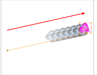
A peg layer is mainly used to control a series of drawing layers, such as clouds, a school of fish or a flock of birds. You can attach them to a peg layer and make them follow a trajectory as a single unit. This makes trajectory modifications much easier and faster. When building a puppet, most of the time you will add a master peg to control your puppet as one object.
In Harmony, you can add pegs to the Network view using the Module Library view and they will instantly appear in the Timeline view. The modules you add to the Network view are synchronized with the ones in the Timeline view.
You can automatically create connections between modules in the Network view without having to drag cables out of the ports.
In the Tool Properties view, the Peg Selection Mode![]() lets you automatically select the peg layers in the Camera view instead of the drawing layers. If you animate with pegs instead of animating the drawing layers directly, enable the Peg Selection Mode to avoid having to select in the Timeline view or use the Select Parent Skipping Effects command.
lets you automatically select the peg layers in the Camera view instead of the drawing layers. If you animate with pegs instead of animating the drawing layers directly, enable the Peg Selection Mode to avoid having to select in the Timeline view or use the Select Parent Skipping Effects command.
| 1. | In the Timeline view, double-click the layer on which you want to set the parameter. |
The Layer Properties editor opens.
| 2. | In the Advanced tab, deselect the Animate Using Animation Tools option. |
| 1. | In the Timeline view, select the layer on which you want to attach a peg. |
| 2. | Do one of the following: |
| ‣ | From the Timeline View layers toolbar, click the Add Peg |
| ‣ | From the top menu, select Insert > Peg. |
| ‣ | Right-click on the layer and select Add > Peg. |
| ‣ | In the Module Library, select a Peg module and drag it to the Network view. |
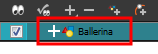
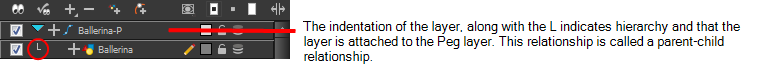
The layer that was originally selected becomes a child of the new parent Peg layer. The new Peg layer automatically takes the name of its child layer, with the addition of the suffix -P.
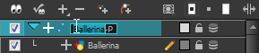
| 3. | If you intend to add multiple pegs or if the layer name that was added to the peg does not accurately represent the content of the Peg layer, you can rename it. Clicking the layer name and type in a new name. Or double-click the layer and type a new name into the dialog box. |
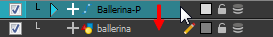
| 4. | If you did not create your peg layer directly above the layer you intended on parenting it to, then drag the layer you want to attach to the peg and drop it directly below the Peg layer. The indentation of the layer below the Peg layer indicates whether it was correctly attached or not. |
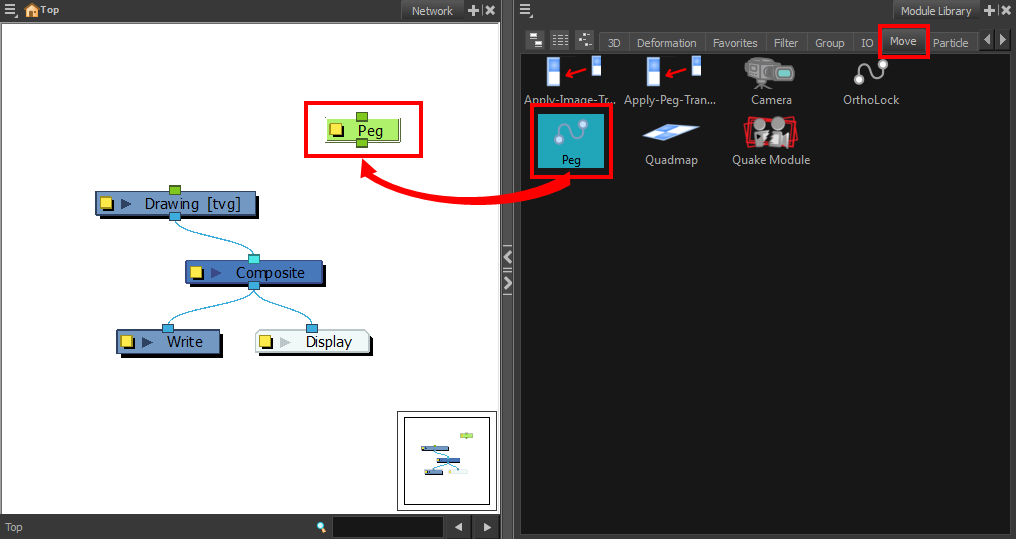
| 1. | In the Module Library view, select the Move tab. |
| 2. | Select a Peg module and drag it to the Network view. |
| 3. | In the Network view, select the Peg module's output port and connect it to a Drawing or Camera module. |
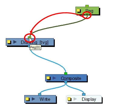
The advanced connections in the Network view are shown in the Timeline view, unless they cannot be reproduced in a timeline layout.
| 1. | In the Network view, position the pointer at the location at which you want to add the new peg module. |
| 2. | Press Ctrl + P (Windows/Linux) or ⌘ + P (Mac OS X). |
The new peg appears in the Network view.
| ‣ | In the Network view, select one or more drawing modules that are not parented to any other module. |
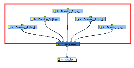
| ‣ | Press Ctrl + P (Windows/Linux) or ⌘ + P (Mac OS X) to add a new peg module to the Network view and automatically connect it to the selected modules. |
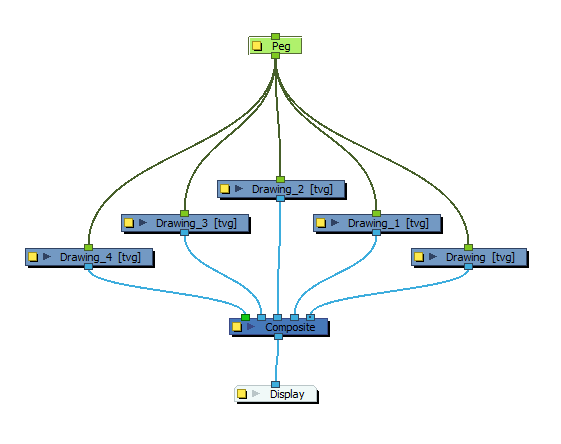
| ‣ | Press Ctrl + Shift + P (Windows/Linux) or ⌘ + Shift + P (Mac OS X) to add a peg to each module. |
| 1. | In the Tools toolbar, select the Transform |
| 2. | In the Tool Properties view, click the Peg Selection Mode |
| 3. | In the Camera view, select an element parented to a peg. |