Network View
In the Network view, you can connect effects and compositing modules to form a network, also known as a node system. This view is very useful for rigging puppets, creating advanced effects and having a clear view of complex scenes. The organization and order of the modules determines the flow of data during the compositing process and how your animation elements will be composited.

When entering symbols, the Symbol Stack lets you navigate back to the top and see the hierarchy of the symbol in which you are working.
The main area of the Network view is the node system area where you can add and organize different modules to represent a scene.
The Navigator view lets you pan the visible area to move quickly through extensive node sets.
The Search toolbar is used to find and match a module in the project. The search is not case-sensitive. Once you have entered characters in the search field, press Enter/Return to validate and find the pattern in the module names. If successful, the module is selected and centred in the view. If many instances are found, use the Previous and Next buttons to cycle through each node.

When entering a group, the Group Navigation allows you to navigate back to the top and see the hierarchy of the group in which you are.
Modules
There is a series of modules available to compose the network. Here are some basic types and information about the main modules.
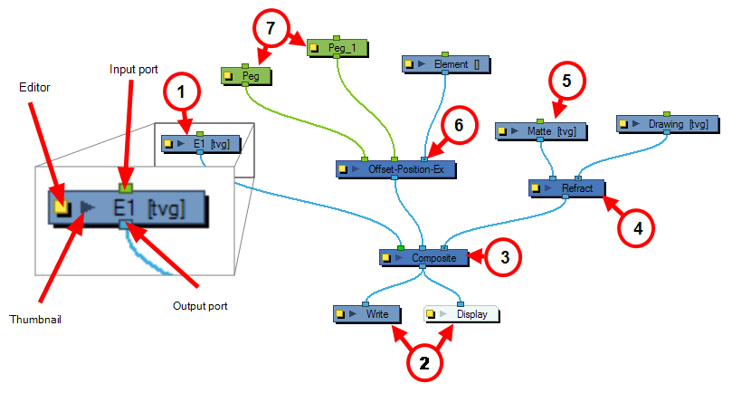
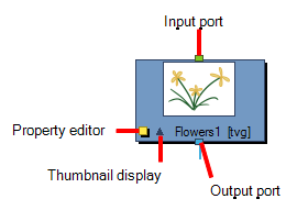
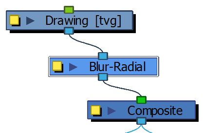
This is an example of an average module, a simple drawing module that represents a layer in the Timeline view. This module has an input port (top) that allows information to flow through it. It has an output port (bottom) that exports its information in a downward flow. On the left is a yellow box that displays the module's property editor, where you can adjust its parameters. Lastly, there is a dark arrow that displays a thumbnail of the module's contents.
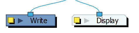
Both the Write and Display modules do not have output ports. This is because the information that flows into them can go no further in the network. The Write module records the images and renders the final output. The Display module captures the visual information and outputs it to the Camera view.
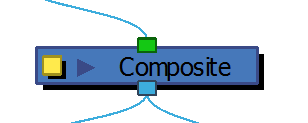
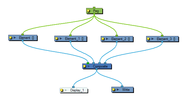
The Composite module combines multiple source images (drawing and effect modules), including all transformations and effects, into a single bitmap or vector image for each frame.
The Composite module layers the images based on the composition order rule. First, the Z-values of the elements are analyzed to determine depth. When multiple elements have the same Z-value, the Depth values in the drawing modules are used. If the Depth values are also the same between elements, the composition order is determined by the cable order of modules on the Composite module. By default, modules connected to the right are rendered below those connected to the left. You can override this default in the Composite module editor—see Composite Module. The Composite module is an example of a module that can have an infinite number of input ports that can take in multiple, individual sources of information. The leftmost input port on the Composite module is always green. This lets you know that, in terms of stacking order, whatever is plugged into this port will appear on top of the composite after the Z-depth is taken into account.
An Effect module can often have two input ports. The right input port is for the drawing layer that is to be acted upon by this effect, while the left port is usually reserved for a matte.
A matte, also called mask, is the shape that will be used by the effect module to modify the original image. The effect will only be applied where the matte overlaps with the original image. Sometimes the matte will act as a negative shape that the effect will exclude. This all depends on the nature and editing properties of the effect.
Some effects contain three input ports. If they are green, then they require a Peg module connection (coordinate and value information). In the case above, the effect can accommodate two pegs.
The Peg modules control the transformation of elements (position, scale, skewing and rotation) over time. The green ports at the top and bottom of the module indicate that it accepts position information and can then pass this information on.
One peg can be used to control many different modules or one module can accept more than one peg. In a situation like the latter, one peg might be used to modify the rotation, while the other used to modify the position of the effect and then animated differently over time.